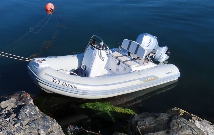
In late 2017 I found the YouTube channel “MV Dirona” and was fascinated with the design of this motor yacht. The owners, James and Jennifer Hamilton, also runs a very nice blog with lots of posts about their adventures cruising the world. Maybe it was the way it manages to look like a big ship although it’s only 52 feet, and that everything about it breaths ruggedness and ocean capability in comparison with many other motor yachts in similar size which main focus is to look fast an luxurious. After completing the design and printing of the radio controlled Combat Boat 90, I had found the perfect next project!
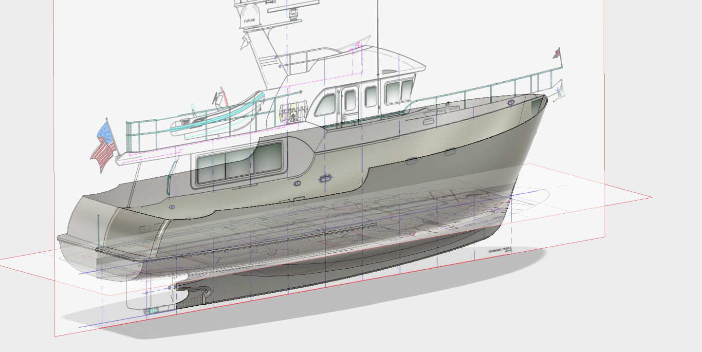
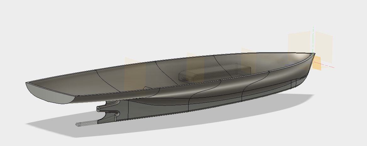
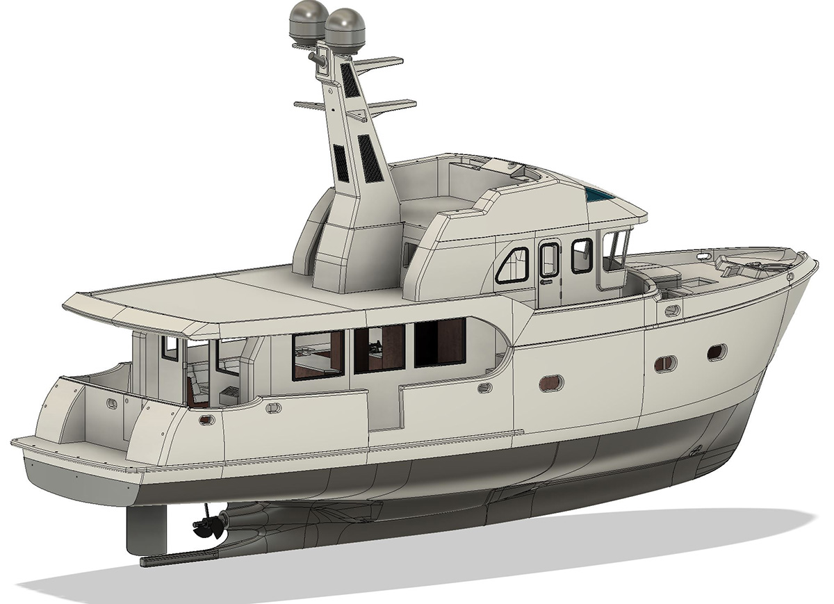
The most fundamental requirement for a project like this is good 3-view drawings. After some googling I managed to find good enough drawings that could be imported into Autodesk Fusion 360. They were then scaled to the chosen size, in this case 1:24 to make it the same scale as my previous project, the Combat Boat 90. As with all complex 3-dimensional shapes, 3-views does not give enough information to draw the shape of the hull accurately, so a lot of improvisation is required if the drawings lack cross section views. After many attempts and re-designs, the hull started to take shape.
Two major bad decisions!
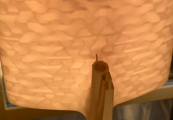
With this project, I made two decision early on that I would come to regret, a lot. The first was the idea to make the hull 5mm thick and print it hollow with a thin grid-like structure inside (known as an infill to 3D-printing nerds). In the picture above, the infill structure is clearly visible with sunlight shining through the semi-transparent PLA filament. There were basically two problems with this, one being the light that more easily can penetrate through a hollow structure like this but also if there is small cracks in the outer shell, water can enter the infill structure and be very hard to detect and dry out. This happened in the area around the bow thruster duct.
The second decision I made that I had to regret later was the choice to integrate as much as possible of the structure in the initial print. This meant that it was later very hard to get access to areas inside the boat once the parts were glued together. This was possible to address later by opening up hatches, mainly in the bow to be able to access the bow thruster area. The first problem meant I was forced to paint all major parts with multiple layers of paint in order to prevent light from shining through.
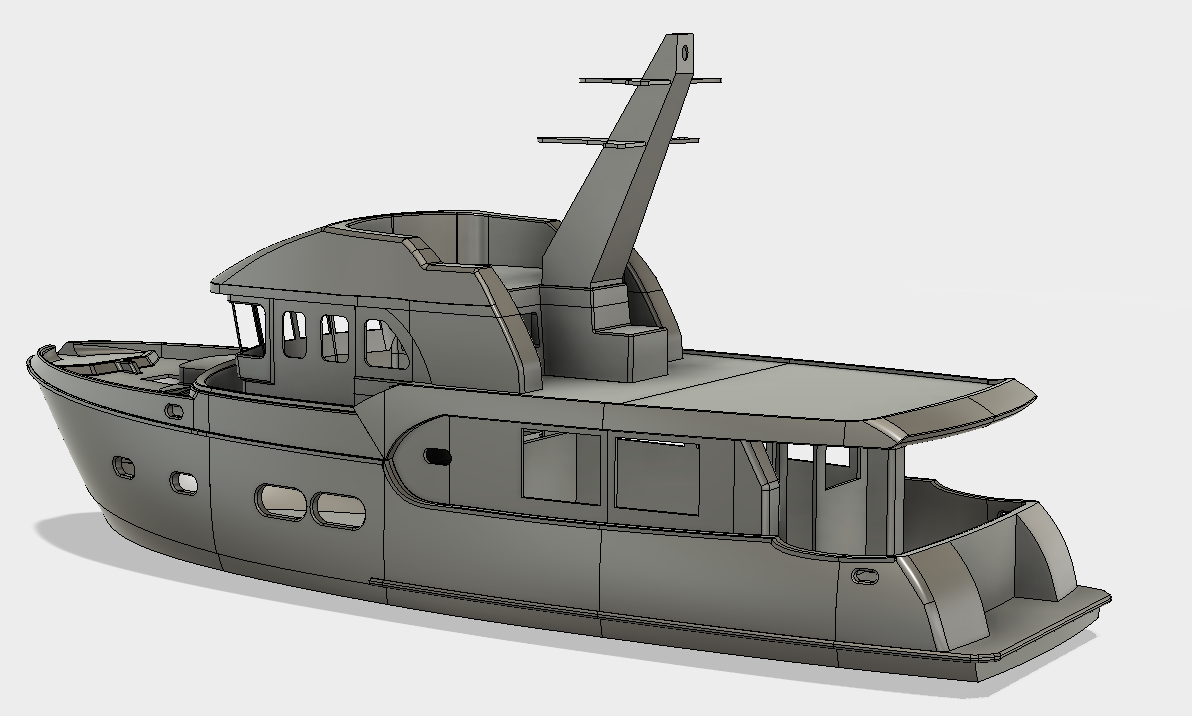
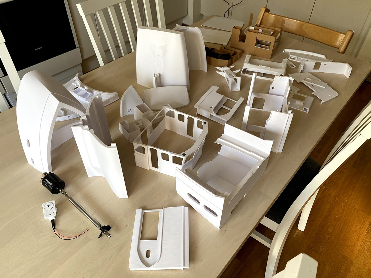
The project was divided along the water line into two major segments, the lower part of the hull and the super-structure. Each of these were then split in 5 sections so that they could be printed vertically. Once printed, the lower hull was glued together separately from the upper structure so that engine and electronics, rudder assembly and cabling could be installed before the two major parts were glued together.
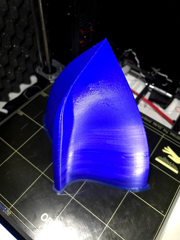
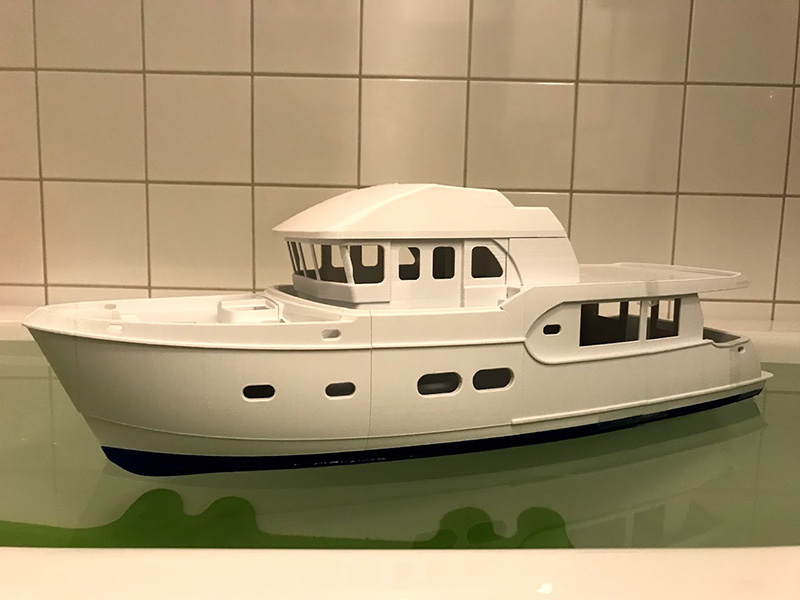
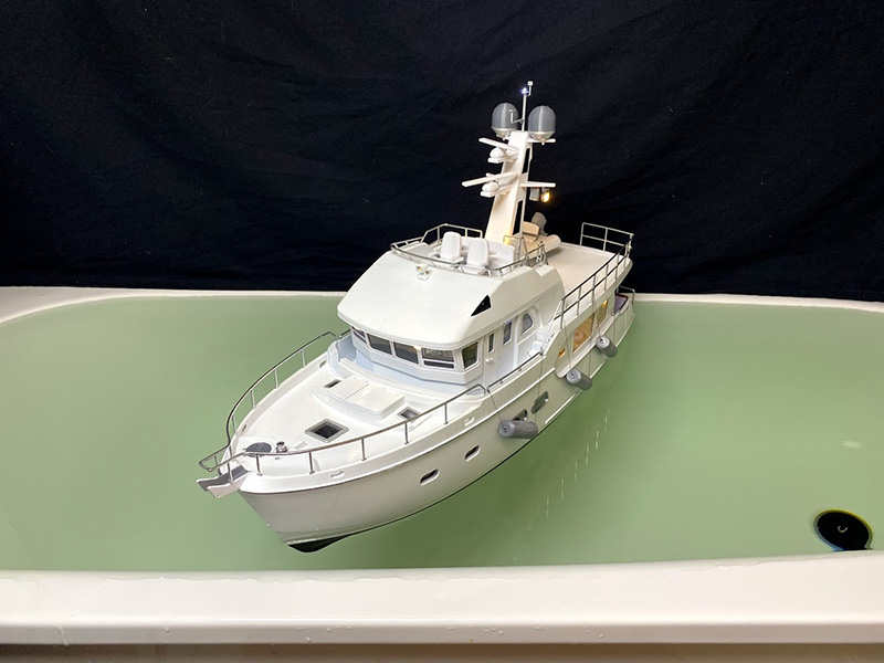
The first prototype was printed during the spring of 2018 and came to the level that it was tested without equipment in the bathtub. But as with so many other projects I lost interest and it ended up on the shelf in favor of other projects, especially the 3D-printed radio controlled Koenigsegg Agera RS.
Turning point – inspiration!
In the fall of 2019 I remembered that I had not visited the mvdirona blog for a long time. Last time I checked, they were in northern Norway and even if that’s pretty close to my location (Stockholm, Sweden) on a global scale, I concluded it was still too far to go just to visit. Never for a second did I think they would choose to travel all the way up the Baltic sea, far into Finland, back past Åland and into the Stockholm archipelago. There they (unknown to me) had spent several weeks within biking distance from my home!
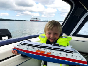
Now when I again visited the blog, to my enormous frustration, they had left Stockholm, past within a couple of hundred meters from my home! and continued through the canal system known as Göta Kanal that connects the east and west cost of Sweden. They were now almost all the way through, moored close to a town called Trollhättan. Still pretty far from my home, this was at least within reasonable range so I dropped an email and was told they planned to stay a couple of days in Trollhättan and that I was welcome to visit. So I grabbed the less-than-half-finished prototype, jumped in the car and drove for 5-6 hours down to Trollhättan and back in one day (totalling 1000km). A crazy car ride for sure, but totally worth it!
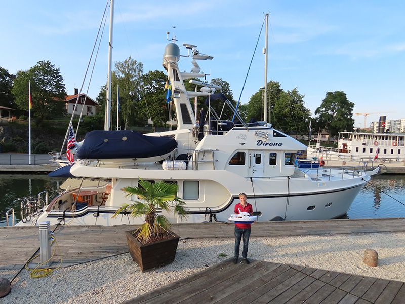
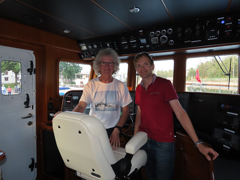
A big thanks to James and Jennifer (and the cat Spitfire) for their warm welcome, their hospitality and for their decision to share their remarkable adventure with the world through their blog. It was remarkable to think of the fact that here they were in a small canal in the middle of Sweden, coming all the way from Seattle! Although this would seem a perfect opportunity to take pictures for the build, I very much preferred to spend this opportunity talking to them as I know their blog contains all the pictures I would need.
Armed with a huge amount of inspiration and motivation, I went home to continue the project. It’s probably easy to think I continued to print parts and glue them together? In reality, during all this time that the project was collecting dust on the shelf, I had learned a lot and came up with a lot of changes I wanted to make and details I wanted to add so I gave the already printed prototype to my son as a toy and decided to print an entirely new one.
I completely remodeled the hull below the water line to increase the volume, added bow thruster and made changes to adapt it for a propeller shaft assembly I found on eBay.
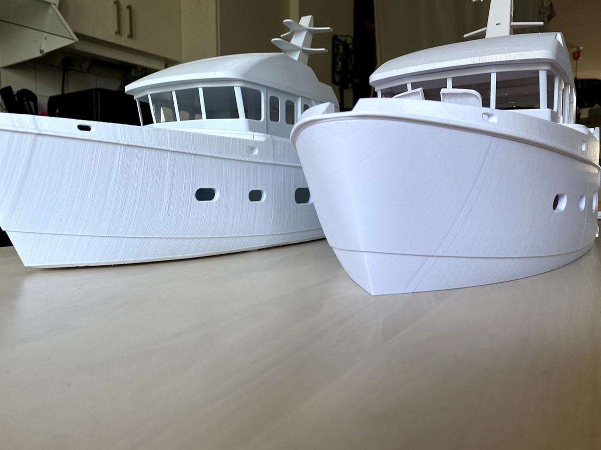
The first prototype was printed on my first printer, a Prusa MK2. While the project was idle, I purchased an MK3S and now when I had printed the reworked model and placed them side by side, the quality difference of the print was very much visible!
Paint or plain print?
With most (if not all) previous projects I liked to keep the printed looks and used the filament colors instead of doing all the work needed in order to sand, prime and paint. Not to mention the fact that I live in an apartment with no hobby-room and especially no workshop so painting is not easy. But after visiting MV Dirona, I decided to go for a full on painted print this time. In fact, I would probably have been forced to do that anyway because of the very transparent nature of the filament meaning any light sources built in would look super-weird shining through all the walls!
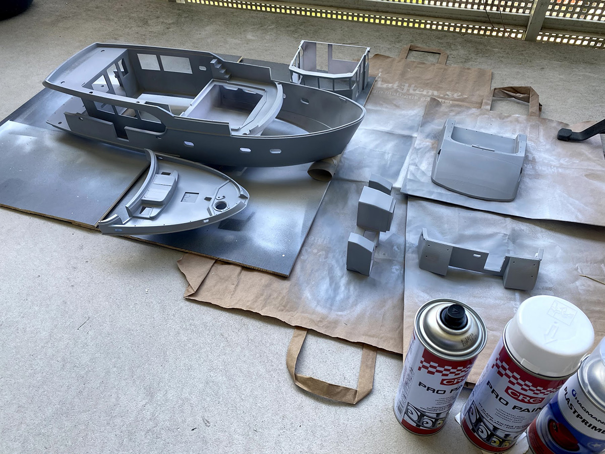
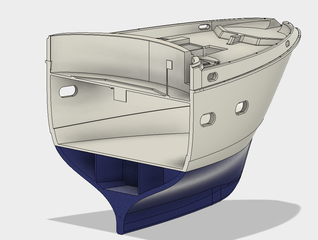
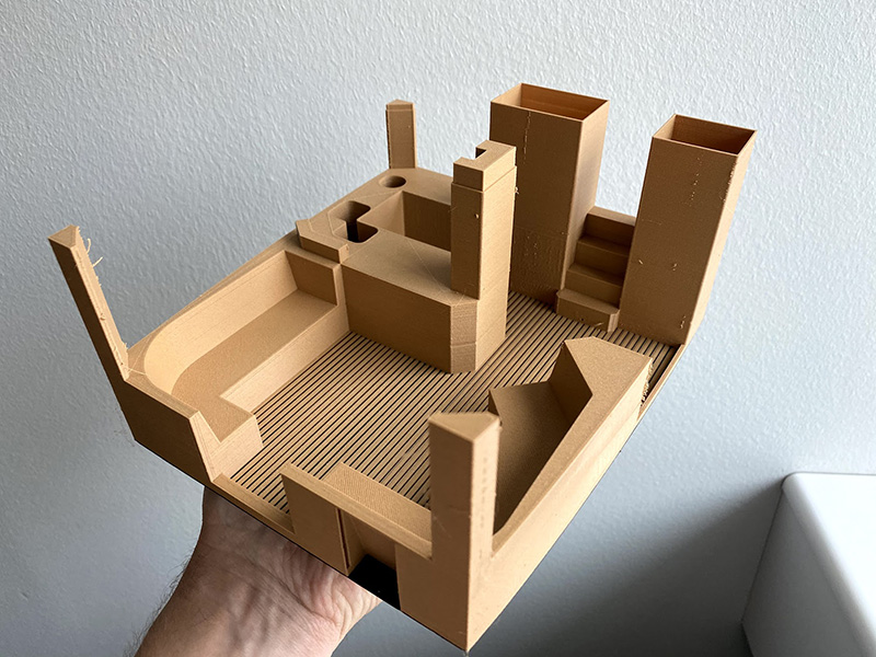
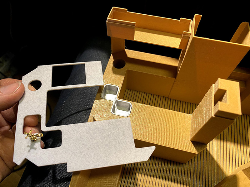
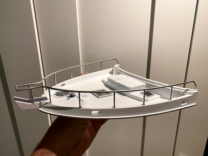
Here some major parts has been primed ready for final paint. A major re-design feature is clearly visible here. I divided the bow section so that the deck can be lifted off to allow access to the bow thruster compartment. I also placed receiver and other electronics in the bow which is now easily accessible through this hatch. To access the motor installation requires the removal of the flybridge, roof and to lift up the saloon interior module so being able to access the RC-equipment in the bow instead made things much simpler.
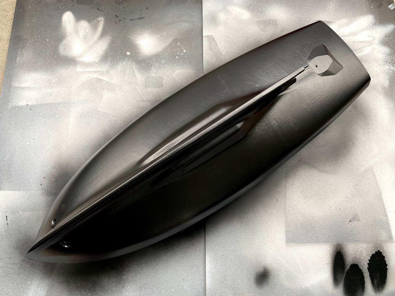
An advantage of finishing the lower hull separately was the fact that it could be painted with the final black paint before the sections were glued together.
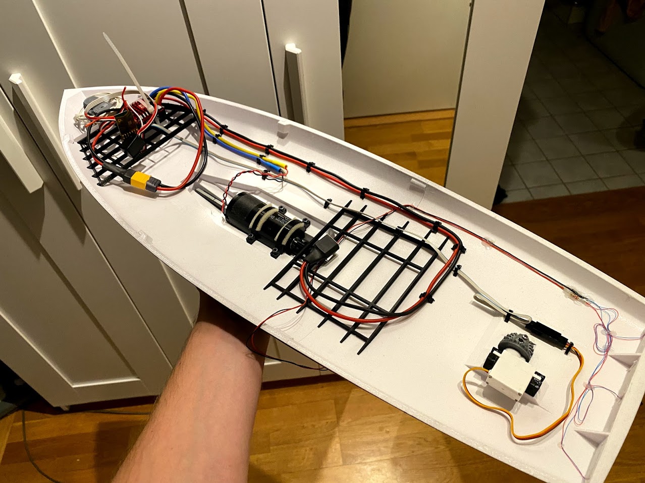
I first installed a 36mm DC-motor from Hobbyking meant for RC-cars. However it was so powerful that even the slightest touch of the stick made it shoot of like a rocket! I realized it was too powerful and digged out an old discarded maxon RE36 DC-motor from work. It was the total opposite, having a winding made for 48V and a low speed constant of 110rpm/v, it is almost too slow so the hunt is on for a motor with higher speed constant. Ironically, this RE36 probably gives the model a very realistic behavior where you really need to plan your maneuvers as it takes several boat lengths to stop even at full reverse! I rather have a bit of extra power margin so will change the motor eventually.
Interior
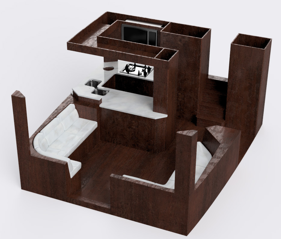
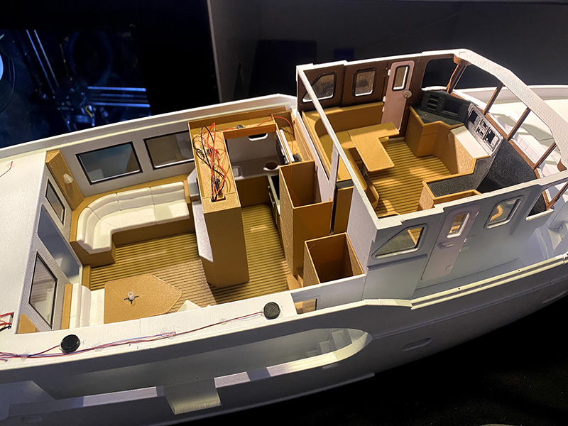
The interior was designed to be easy to lift out of the model, providing access to the compartments underneath.
These modules were printed in a wood-imitating PLA filament called Polywood from Polymaker. In the print above, I also included dual-color print with black PLA as bottom and imitating wood floor with black PLA lines between the planks. This was printed on a dual-print head Ultimaker 3 printer as my Prusa MK3S only has one print head.
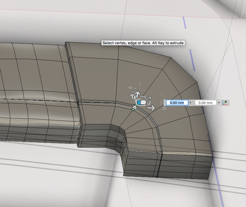
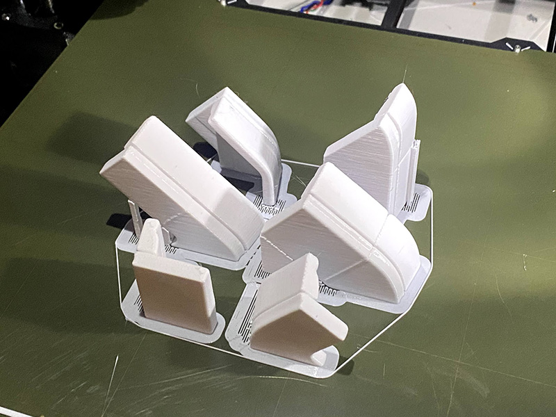
The soft parts of the sofas was modeled using the free-forming tools in Fusion 360 to give them that organic look. Print bed orientation is always a big consideration when exporting files for print. For the printing process to work, a flat surface is needed to be placed on the print bed and there should be no overhangs that causes troubles. In the picture above, the cushions have been split to have a perfectly flat surface towards the print bed. However it wasn’t possible to avoid all difficult overhangs so some supports were needed. (support: additional structure that the printing software adds, which is later broken off and discarded).
The countertop were printed in a filament that is supposed to resemble marble right out of the printer. It was printed upside down to have the best surface facing upwards. The result was amazing! Unfortunately I don’t know the name of the filament as I received a test-piece without a roll from a friend a long time ago.
The sink was printed in silver PLA with a coat of silver spray paint added for extra gloss. The tap is not printed, it comes from a set of parts for a doll house. As it turned out, the scale 1:24 is actually a pretty common doll house scale which I didn’t know when I started the project!
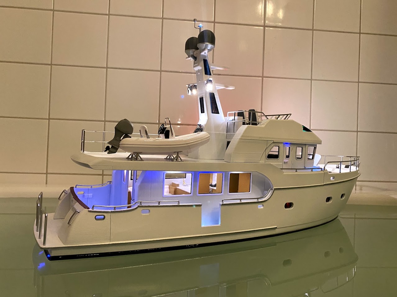
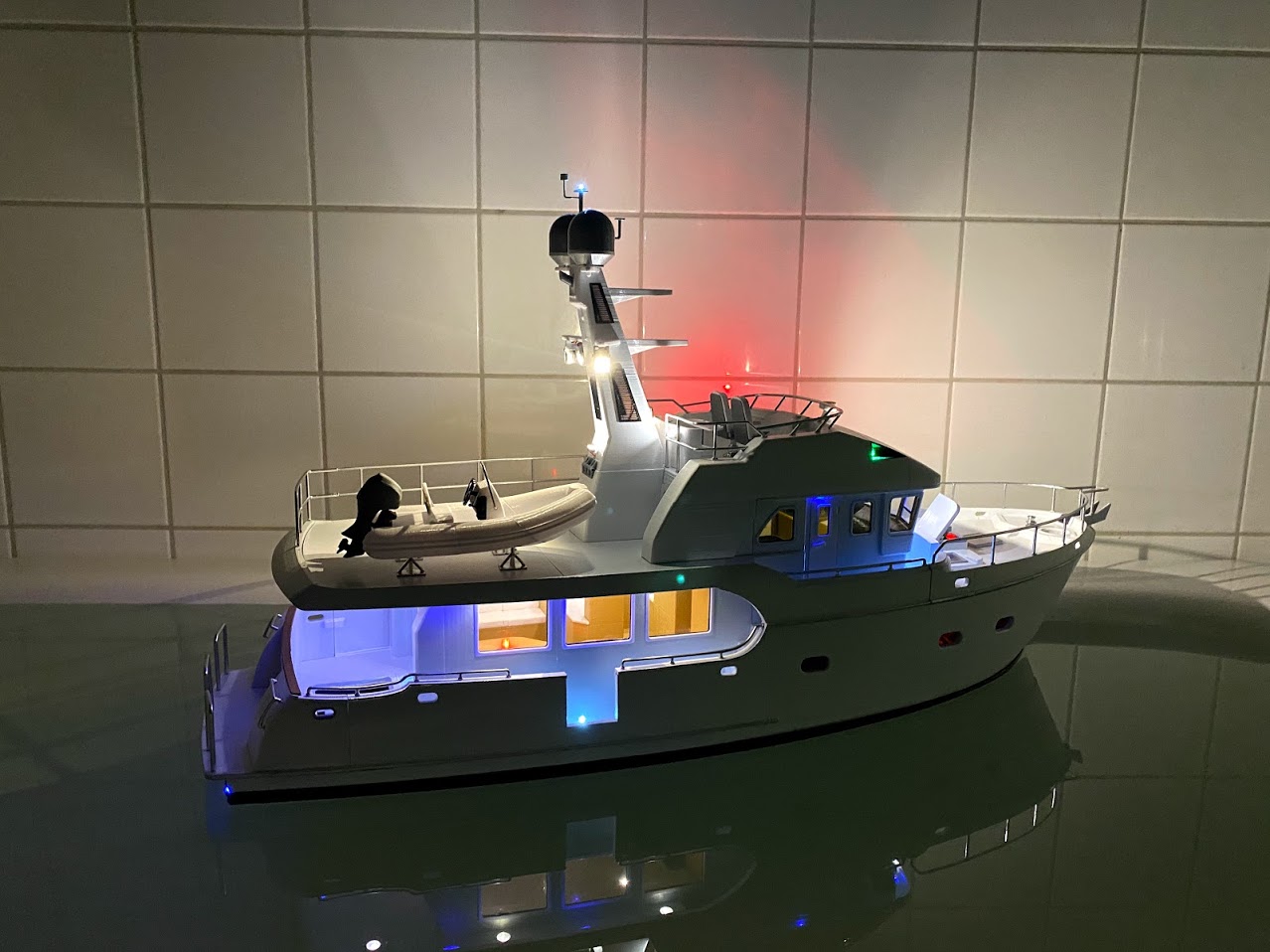
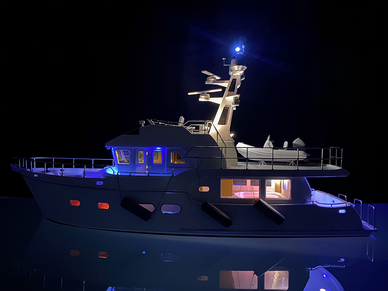
LED’s! lots of LED’s!
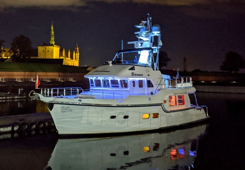
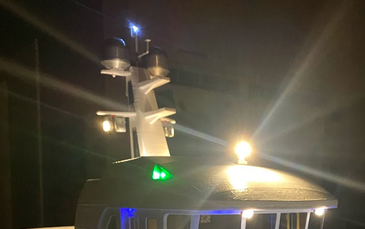
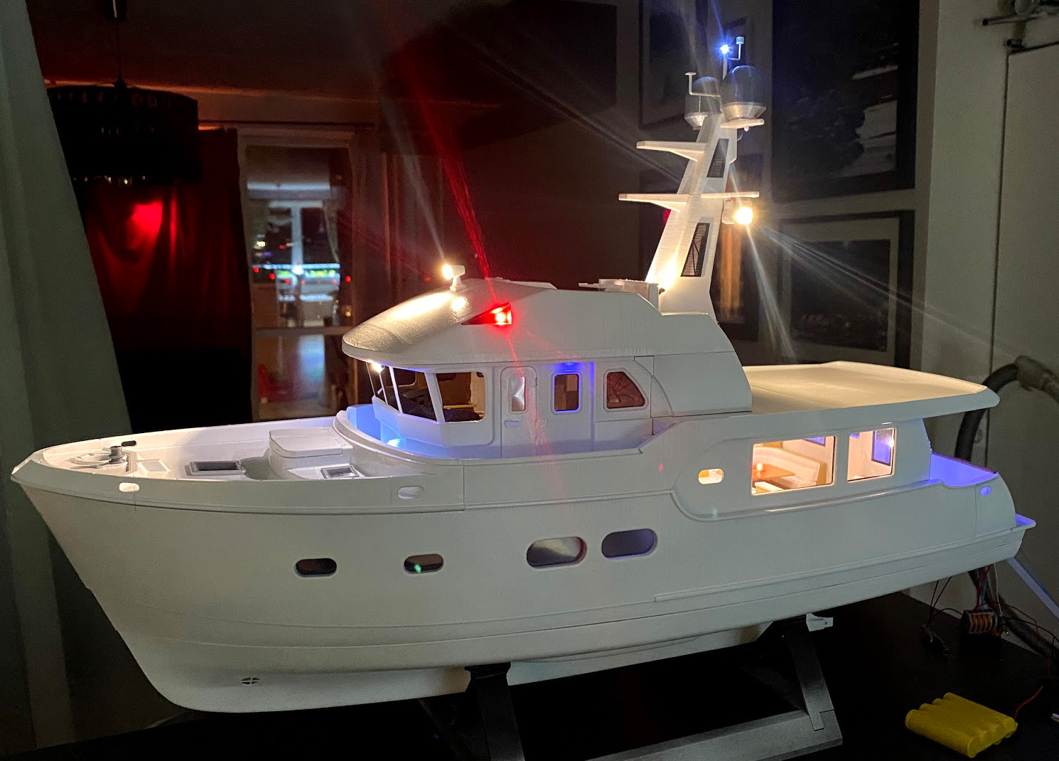
MV Dirona is equipped with lots of light features that makes it look really nice in the darkness. I wanted to re-create this look in the model so it was going to require lots of LED’s! A counter intuitive thing about models is that working lights do more for the scale appearance than the actual ability to move regardless if it is in water, air or on land. An RC-model that moves, but without lights will look “dead” but the same model not moving, but with lights looks alive. Of course airplanes have the advantage that if they are photographed in the air, it’s very obvious that they are working. But even an aircraft will very much come alive if nav lights, beacons and landing lights are added.
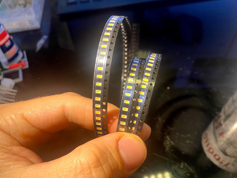
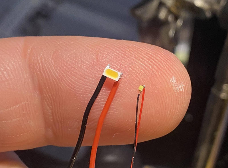
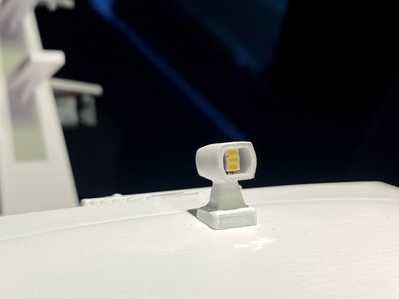
The LED on the left is a 3014 SMD meaning it is 3mm long and 1,4mm wide. The one to the right is 0402 which is 0,04in x 0,02in (1mm x 0,5mm). I have no idea why one of them is specified in the metric system and the other one isn’t. I ordered a roll of the bigger ones in warm-white a long time ago and now I finally had a project where they would come to good use! But since ordering the “big” ones, I started to see lots of pre-soldered extremely tiny LED’s popping up on eBay, Wish and other places for very reasonable prices. I ordered lots of them in different colors and they proved to be extremely useful for projects such as this! I know there are lots of talented people out there that would claim the 0402 package can be solder by hand, but with my equipment it was a no-go so being able to buy them pre-soldered saved the day!
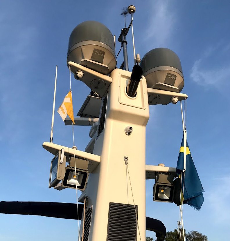
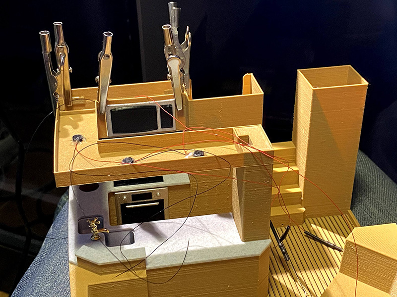
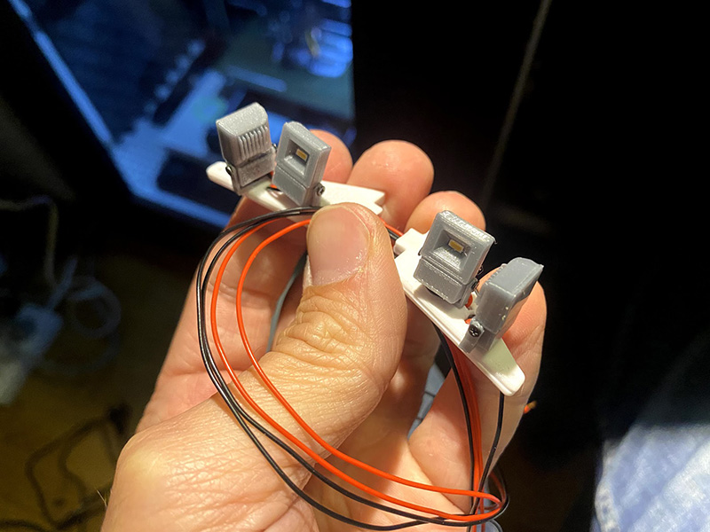
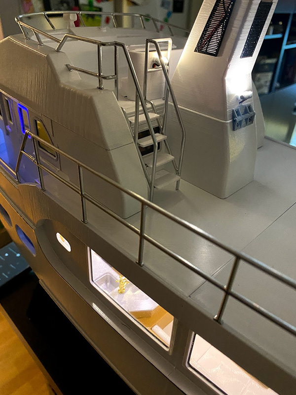
In the mast sits 4 very powerful flood lights for which the 3014 SMD’s worked perfectly.
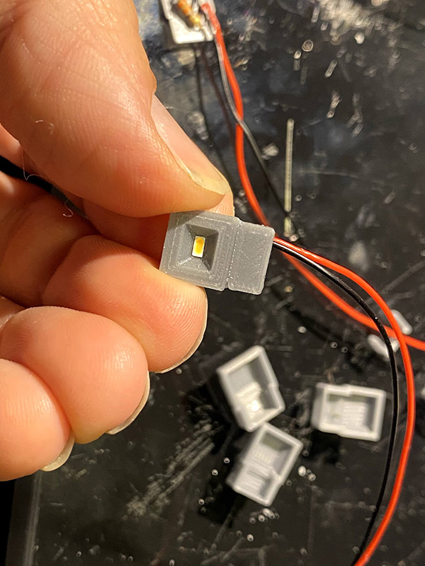
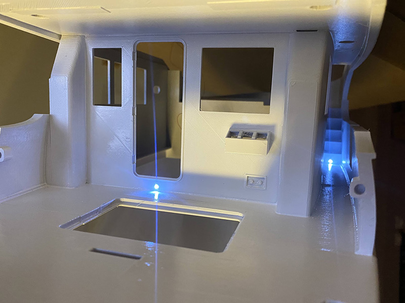
I bought pre-soldered 0402’s with different light color. The cold white was used for the deck floor illumination and the tiny size meant they could be inserted into 1mm holes made in the walls already integrated into the CAD and print! This was one of many changes I made to the CAD before printing the second time. The amazing accuracy of the Prusa MK3s meant that almost none of these holes needed to be drilled out. After inserting the LED’s, the holes were filled with CA-glue to make them water tight. I had to have a battery connected to make sure they were oriented the right way. Once the CA-glue hardened a faulty installation would be beyond rescue!
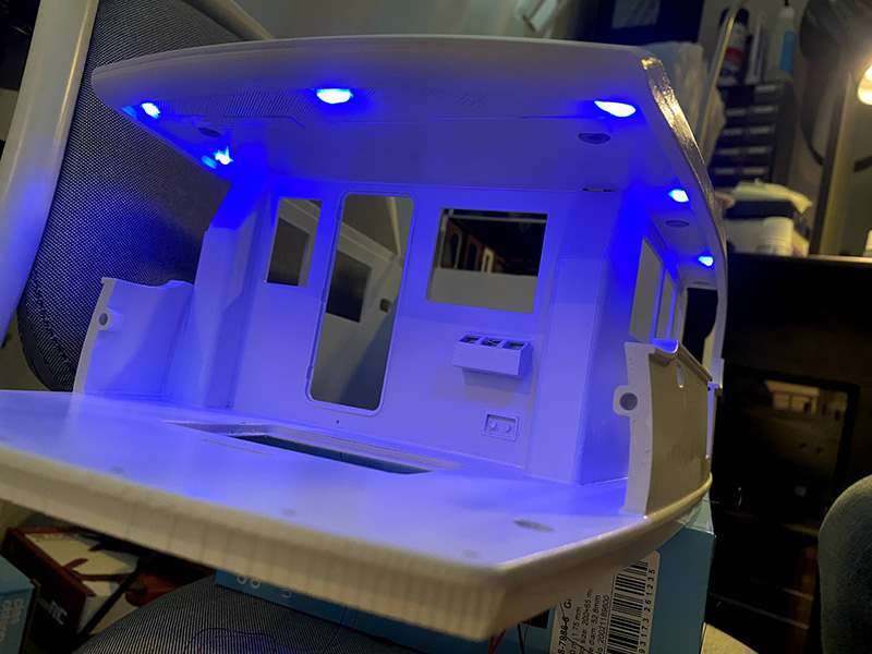
I purchased what I thought was blue/purple 0402’s, but in reality it was pure UV-LED’s. Fortunately, melt glue actually converts lots of the UV-light to visible blue, so each of them got a dot of melt glue over them creating that nice blue mood light I was trying to re-create. Full scale Dirona has blue LED-strips attached to the inner edges of the roof.
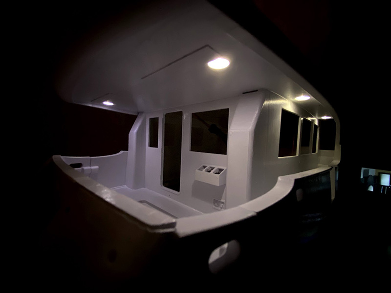
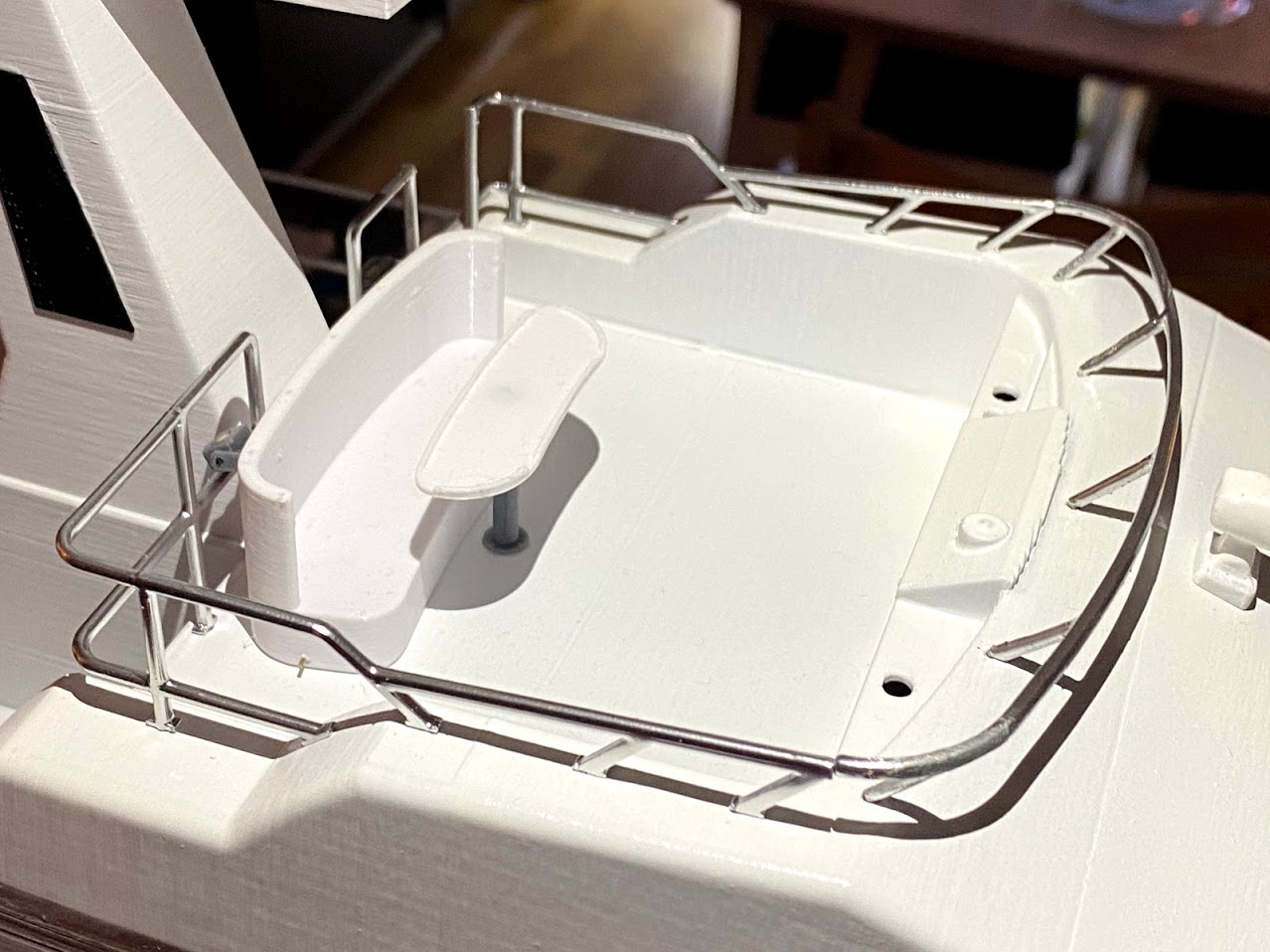
White LED’s are also installed in the roof. Another major design change can be seen in the two pictures above. I realized I had to be able to access the steering servo under the aft floor and made the aft wall removable with magnets to hold it in place.
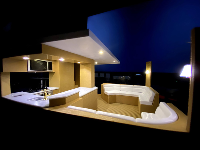
A number of different LED’s where installed in the saloon. They are connected to different channels so that the light display of the model can be changed.
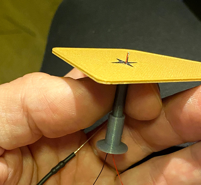
A small red LED was installed in the saloon table with the cables inside the column.
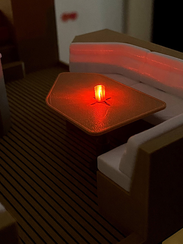
The led sits inside a cup printed in transparent PLA to imitate the looks of a table candle.
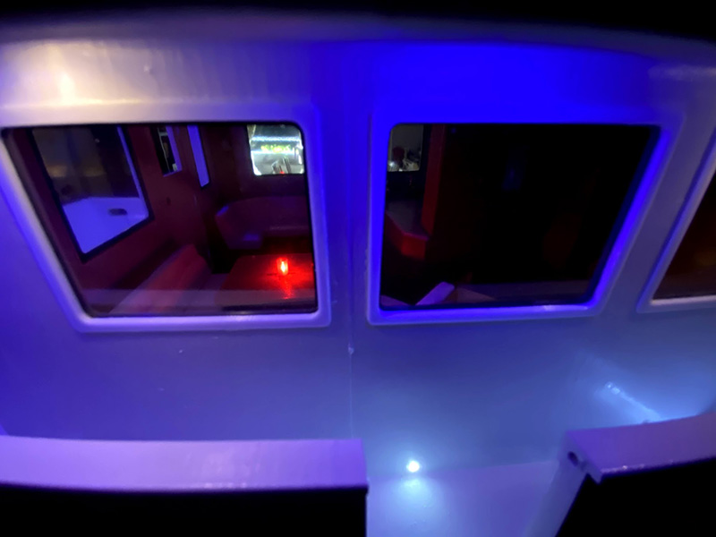
The table candle has its own channel.
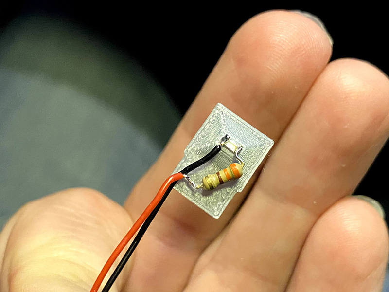
A powerful forward facing flood light was built using 3pcs of 3014’s soldered in parallel. Two additional 3014’s are used to provide flood light for the forward deck.
Custom light controller
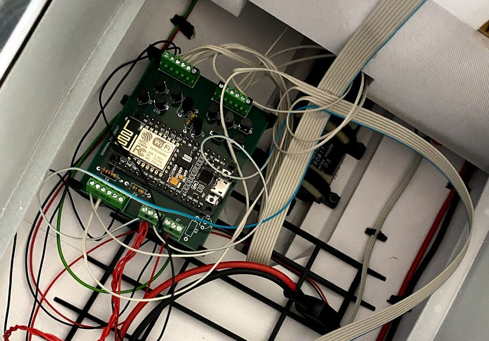
To control the LED’s, I used a NodeMCU. It is a board containing an ESP8266 wifi-module. These boards can be programmed using the Arduino IDE and there is lots of code and many examples available to get started.
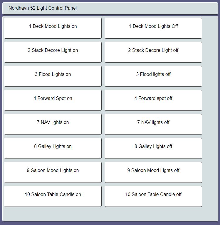
I programmed the NodeMCU to act as a wifi access point to which any wifi-capable device with a browser can be connected. It also contains it’s own tiny web-server with a pre-programmed web interface that is sent to the client device. This interface contains buttons to control the lights.
An important reason for building the light controller wifi-based was that this boat is 99% home decoration and 1% RC-boat, meaning 99% of the usage time it will only have lights on and no RC-equipment running. Because of this, the light controller has its own power input so that it can be powered using a standard USB charger. The light controller board does have an input from the RC-receiver but it’s not used at this time because it’s so much easier to connect a mobile phone to the controller and control the lights that way.
The NodeMCU I/O uses 3,3V and the combined current of all the 40+ LED’s would be too much for the built in voltage regulator. Therefor, I chose to design the motherboard with an open-collector design that means the ground wire of the LED’s are connected to the output of the controller. The LED’s can then be powered with any other voltage as long as the board and the LED share the same ground and the current does not flow through the NodeMCU but instead through external transistors on the motherboard.
This meant that I could connect several of the small 0402’s in series, reducing the overall current consumption and simplifying the wiring, and reducing the number of resistors needed.
But as in all projects, problems always arise where you least expect them. This was no different as the NodeMCU refused to start after assembling the board. Despite checking the schematic and board multiple times and performing tons of measuring, I could not find any errors. After lots of research, I found that several of the NodeMCU’s I/O’s cannot be connected to ground at startup, or the NodeMCU (ESP8266) will refuse to boot and since my designed meant that the I/O’s were connected to ground through the transistors, this meant it refused to start. I had to cut the leads on a couple of the I/Os but at last managed to get 7 channels working. This meant I had to combine some more LED’s than planned. But they still have individual wiring so if I decide to build a new light controller, I can just install it and split the wires between more channels.
Exterior details
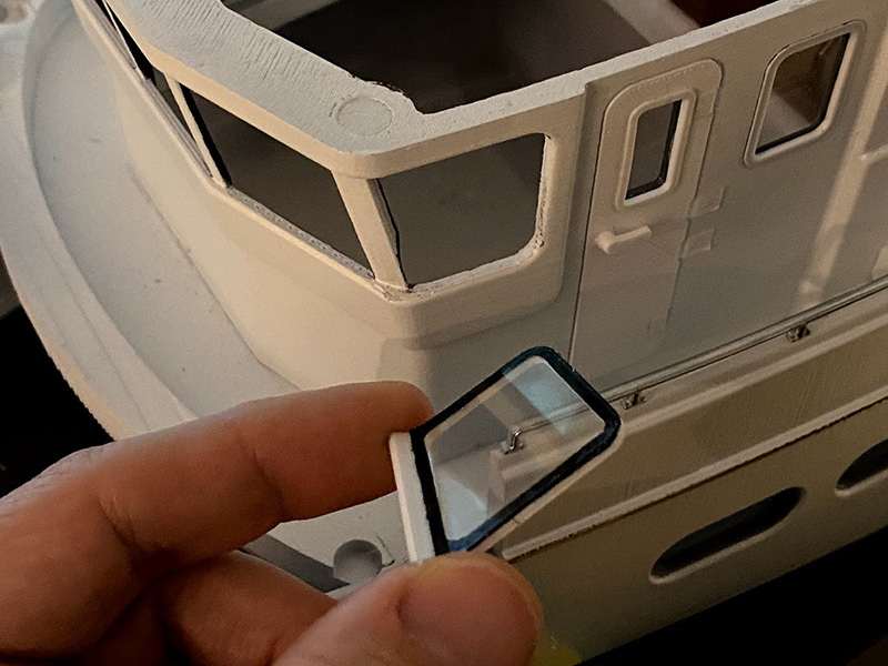
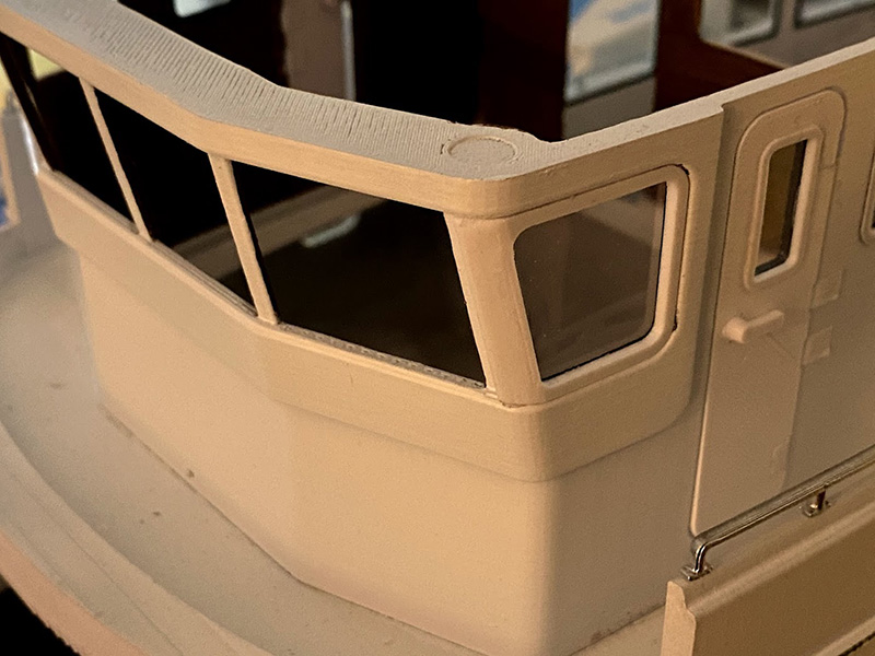
Even with lots of lights installed, it still didn’t look very scale like without details such as grab rails, chrome lines and chrome portlight frames. One very challenging detail is the windows, how to attach them and doing so without contaminating them with glue.
And even when printed and the clear plastic attached, the frames leaked light so I was forced to either paint the inside of the frame area black or add a black printed frame. In the saloon I printed and glued black frames to the inside.
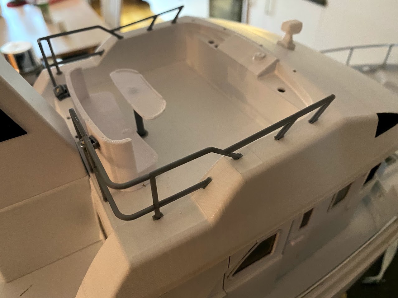
On to another very important exterior detail, the grab rails. This boat has lots of it, and it looks very empty without them. There are several options for how to make scale grab rails from for example aluminum tubes but in this case I wanted to 3d-print as much as possible so I gave it a go, and that was a decision I do not regret!
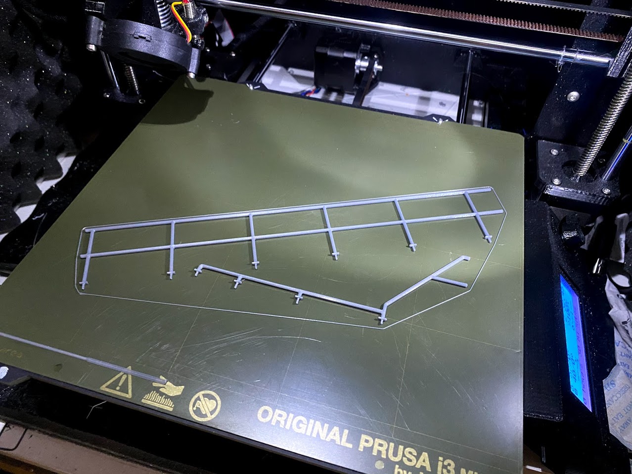
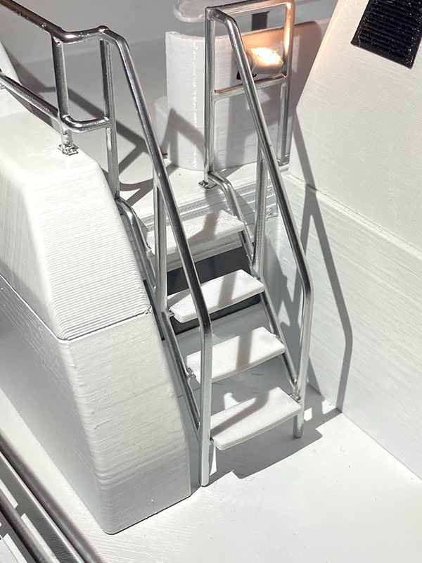
The grab rails were printed in silver grey PLA, and although they could have worked as part of a completely un-painted print, I wanted to up their looks in this case. I found a nice chrome spray in the local hobby shop.
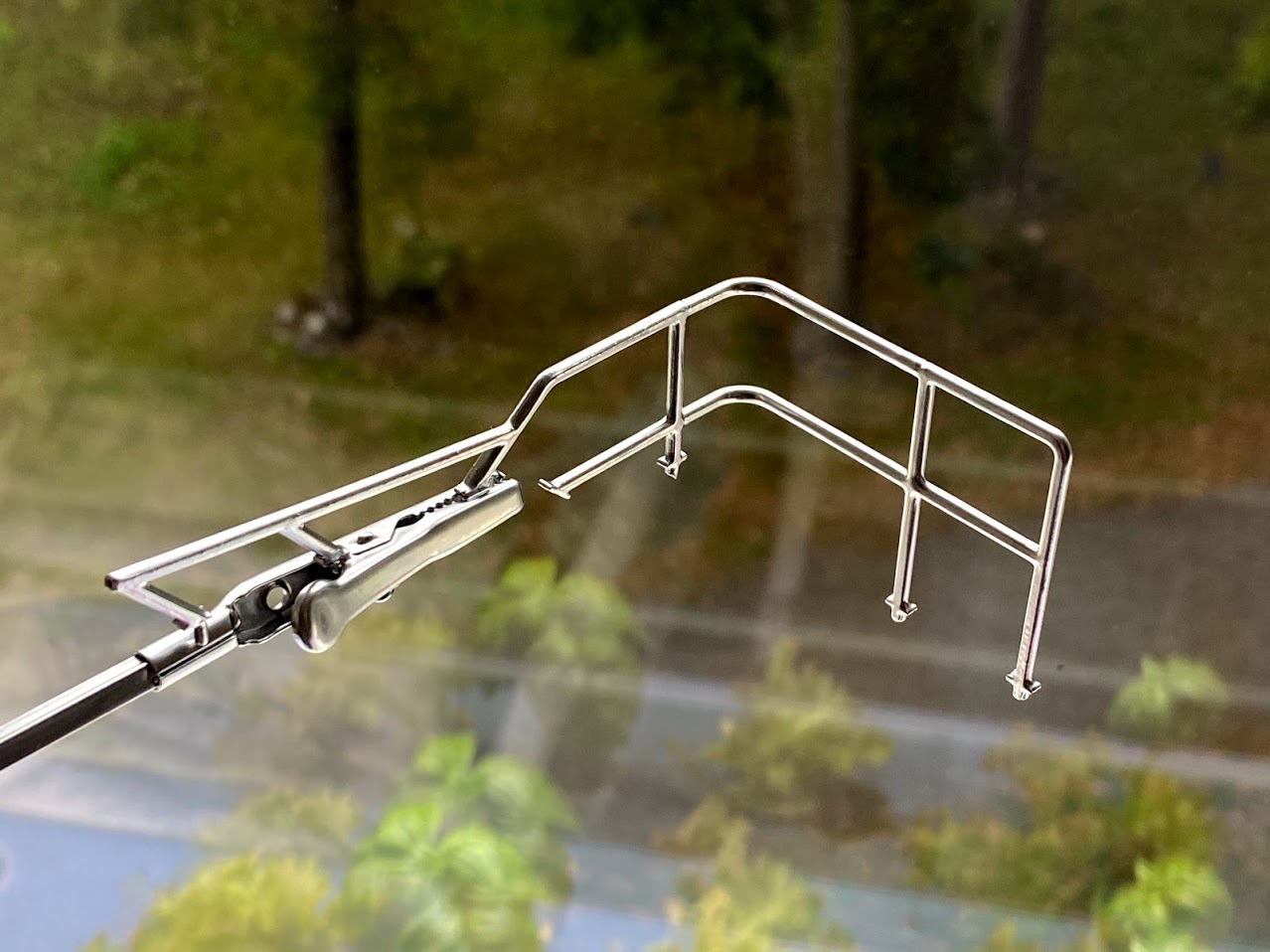
It is hard to believe that the part above was printed on a standard FDM printer! Only downside with the chrome spray is that it’s not very durable. I need to test if it can be coated with some kind of protective clear coat for future projects.
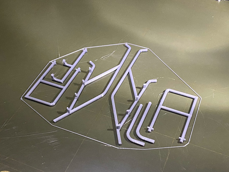
Even though the rails looks round, they are designed with one side having a little bit of flat surface, just enough for them to stick to the print bed.
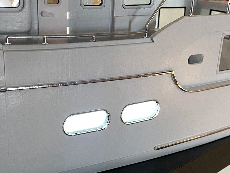
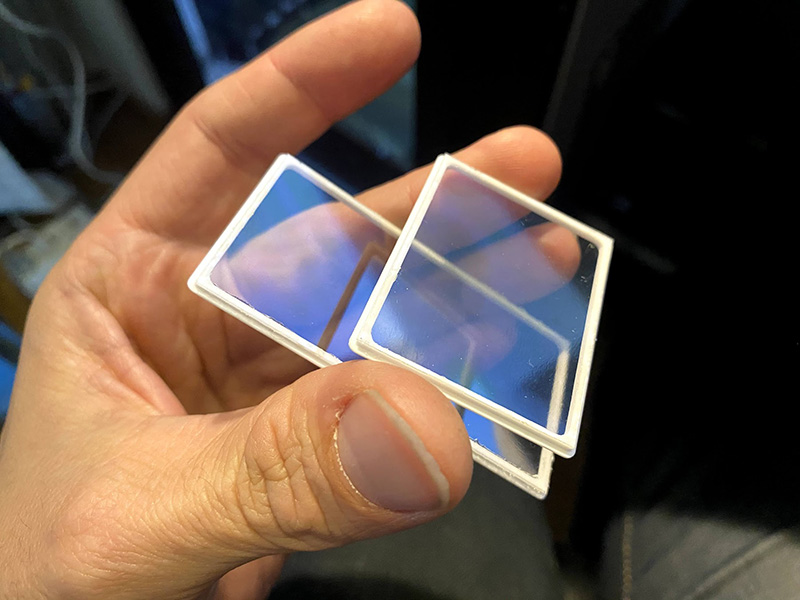
Some other chrome features includes lines along side the hull and the lower port lights. Because of the fact that these are situated close to the water I needed them to be water tight. therefor I first glued a larger piece of clear plastic to the inside of the hull, making sure it’s glued all the way around the holes. After that I added a frame and another piece of clear plastic and finally a chrome painted frame on the outside. There is of course a risk that water will ether between the panes, time will tell. At least it looks better than having only the clear plastic on the inside.
Tender
The large aft upper deck would look very empty without the tender, so I had to do that one as well. One might think that the inflatable part of the rib is the most challenging thing to draw, but in fact it is the outboard engine.
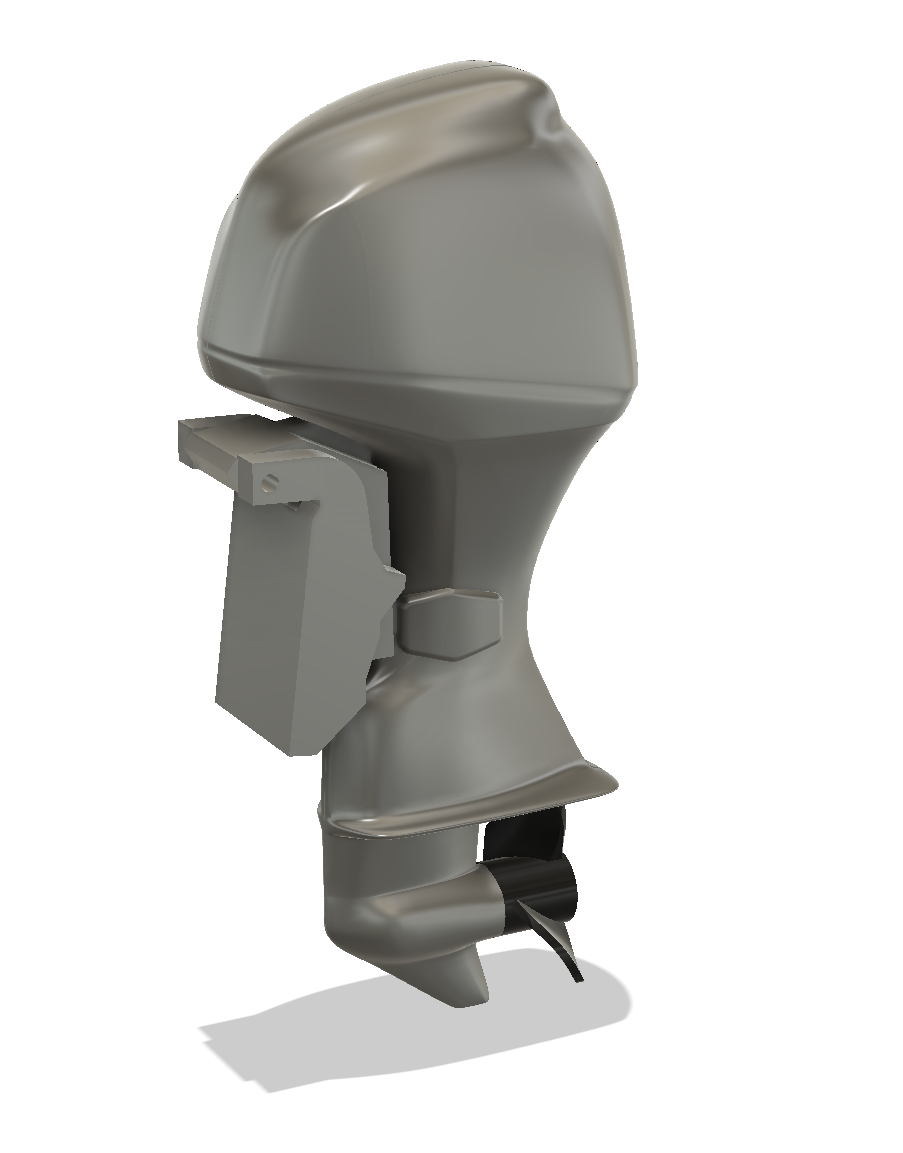
A modern outboard engine is a very complex piece of geometry, and if too many features are left out it will loose it’s scale looks. Here again the free-forming tool in Fusion 360 makes it possible to achieve this in reasonable time. The entire rig of the motor is modeled as one piece, with propeller and mount added as separate parts.
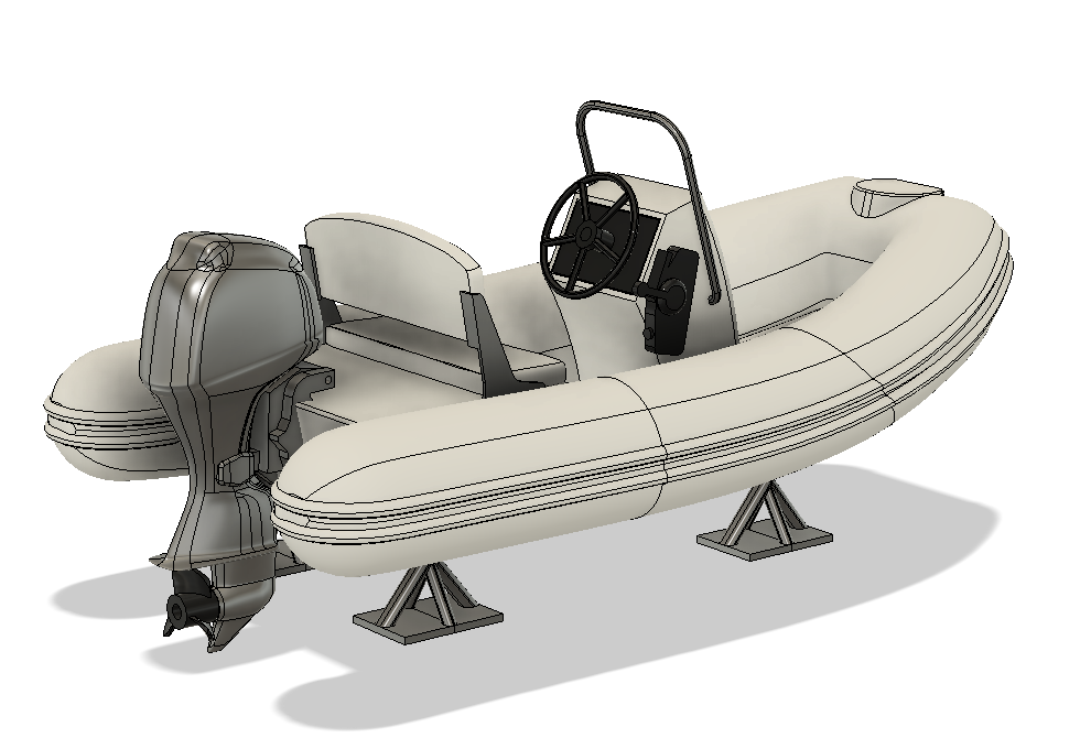
The hull of the rib was also modeled using the free-forming tool.
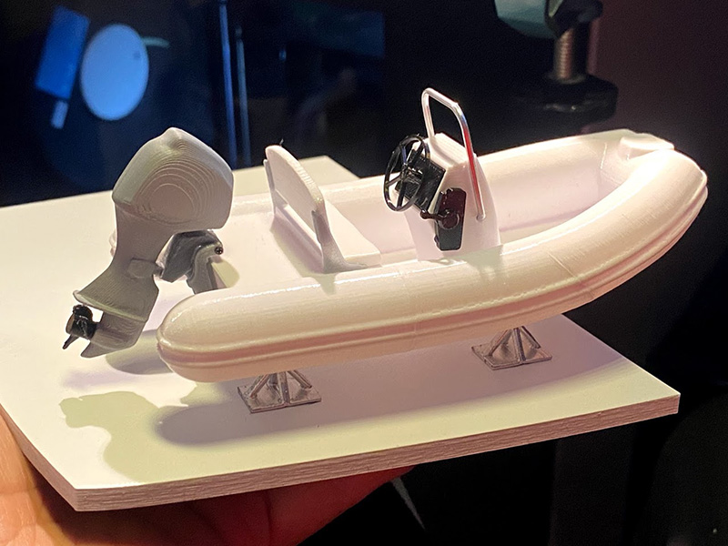
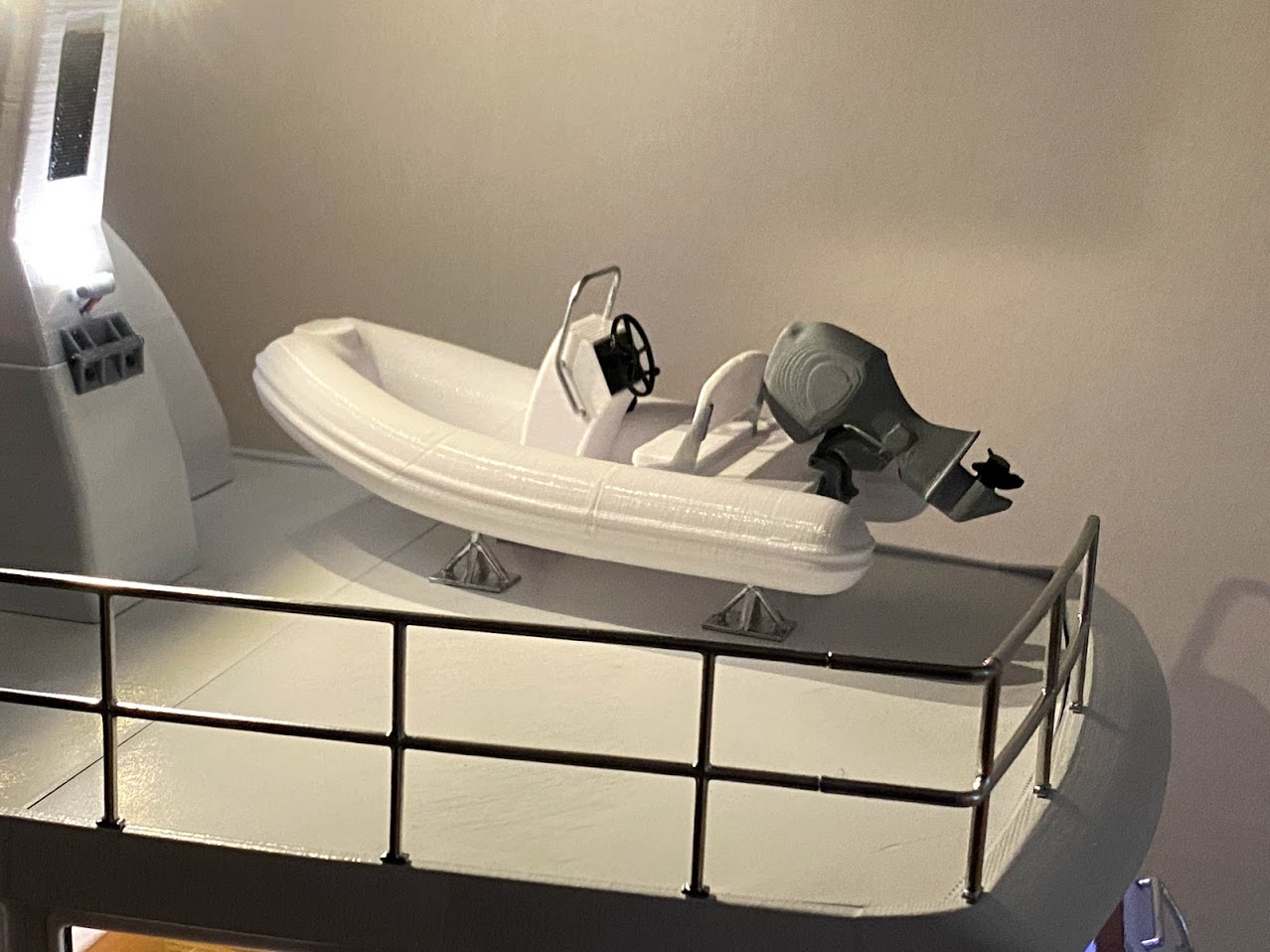
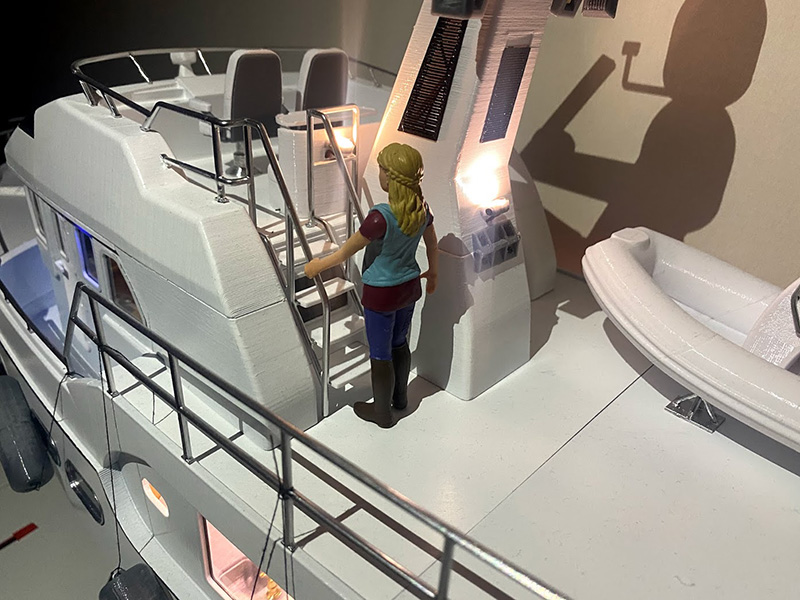
The deck crane is still missing. Would be very nice to make it radio controlled! But at least the deck doesn’t look as empty as it did before.
There are lots of more details to write about in this project, but this post is already getting too long so let’s end it here with a bath-tub photo shoot! At the time of writing, it has not yet been tested outside of the bathtub and with winter outside it might take a couple of months before that’s done. For those of you wondering about STL’s, yes there are over 300 of them and they are not posted yet at time of writing. I will try to do it in some form, but cannot promise when and how. For questions about this project and other things related, please check out my forum at www.depronized.com/board.