Converting a small RC-boat to a cruise ferry!
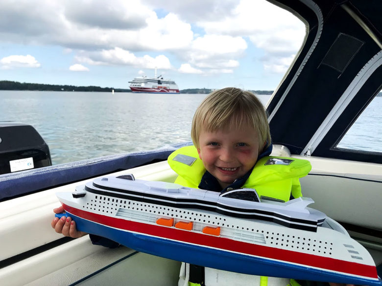
During the summer vacation 2019 my son, then 5 years old, wanted a small RC-boat converted into his favorite cruise ferry: MS Viking Grace.
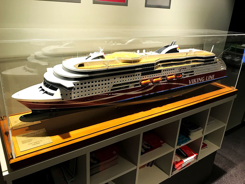
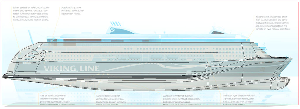
The idea came from when we were travelling with Grace and in the lobby area sits a very nice detailed model of the ship.
What better challenge can you ask for when the 3D-printer had been brought to our summer house? Said and done, the project was started.
Any CAD-project always starts with gathering information. When it comes to scale models, detailed scale drawings are the most important and most valuable tools. They can be imported into Fusion 360 as Canvases and placed on a plane. Fusion has a very easy-to-use calibration tool that lets you select two points on the canvas and enter the dimension between and it will automatically resize the canvas to fit. Selecting a suitable size is usually quite tricky as it’s very hard to visualize something that doesn’t yet exist physically. For this project, I decided to go for a length of 60cm.
Such a relatively small model would roll a lot from every little wave so in order to stabilize it, I increased the beam slightly and increased the size of the submerged parts of the hull. In retrospect, the widened beam didn’t really look good, but it was very hard to see that in the CAD-model because when looking at it in CAD, you’re looking at its whole height including submerged parts giving it other proportions than later when parts of it is hidden under the water.
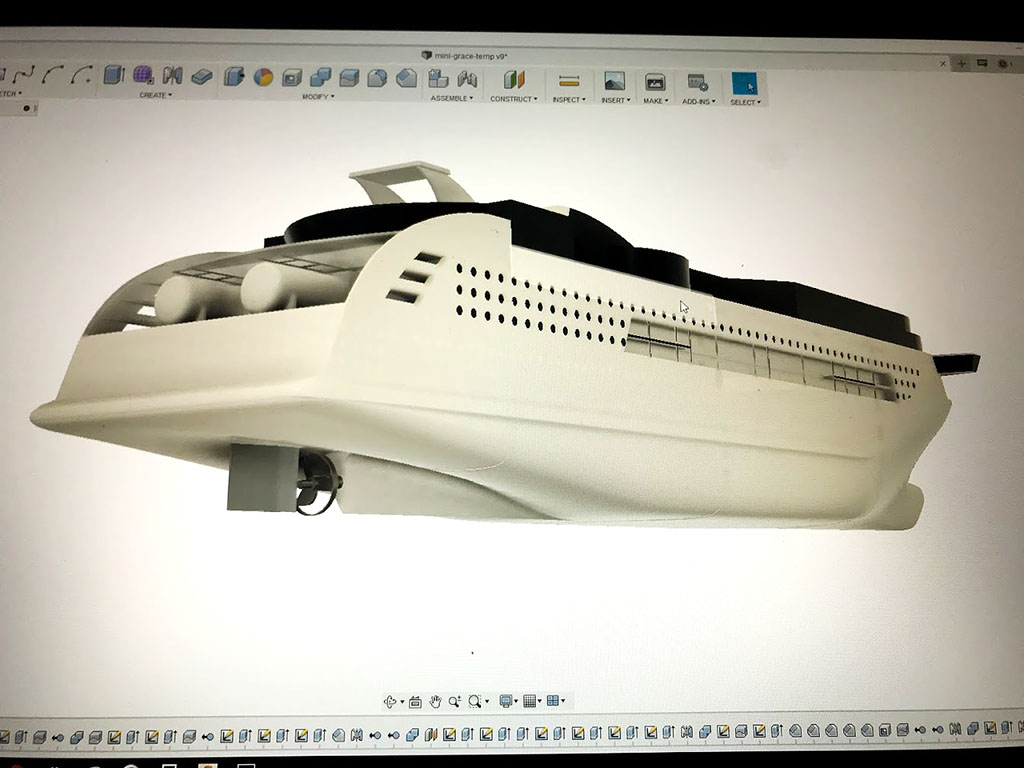
For this project I used the sculpting tool in Fusion for the entire hull and traditional methods only for the superstructure and a few details.
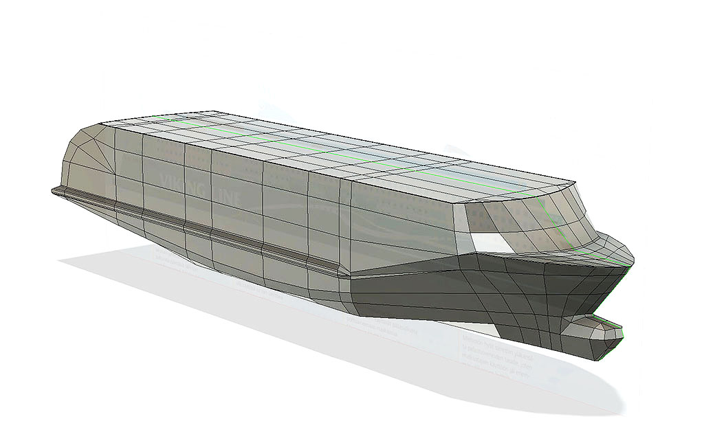
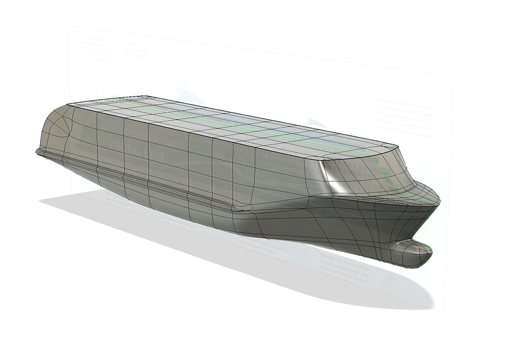
Working in the sculpting environment can be very confusing for beginners with weird behaviors and shapes that just doesn’t do what you want. The key to this is to work in box mode (Utilities -> Display Mode). It is in this mode you can see what is really going on and it is here you can fix it. My general rule is that if it looks good in box mode, it looks good in rounded mode as well, but not necessarily the opposite. Especially if you get errors saying you have overlapping surfaces, you will be able to see and correct those in box mode. I start with just a big box, make sure
I add symmetry along the center line (green line in the picture) so that I can work only on one side of the hull and the other side is automatically mirrored while I’m working. This is important as I need to see the result during the process to get the proportions right.
Once I’m happy with the result I click OK which makes the hull into one big solid body. Next step is to hollow it out, and here one can run into problems if too many small details are incorporated. This is why I like to do this quite early in the process and add more details with traditional sketches and extrudes. Problems with hollowing out is often due to tight corners and thin parts where the system cannot work out how to hollow it out inside.
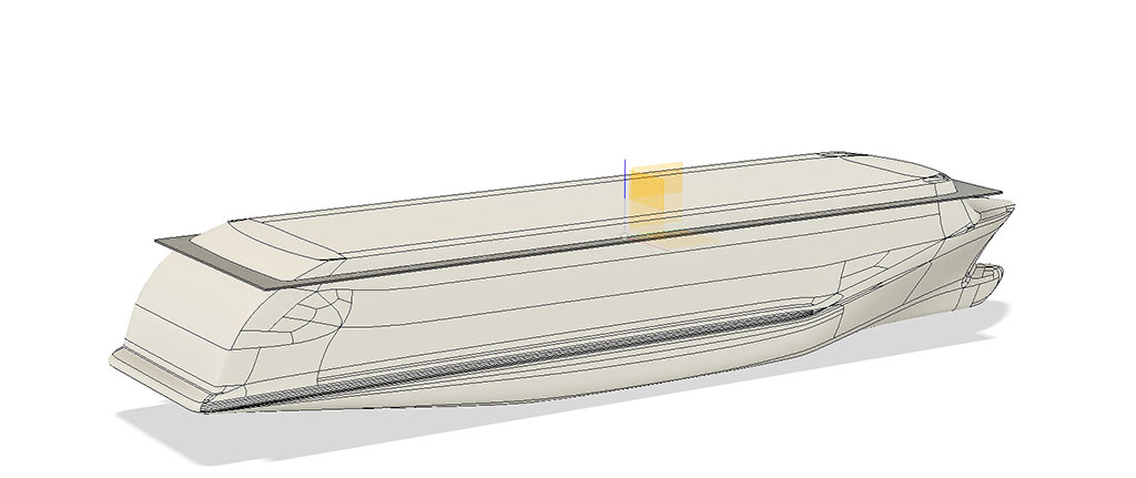
A sculpted body can be a bit tricky to work with as it often doesn’t have perfectly flat surfaces that can be used as references and it can be hard to connect parts to it. It’s also risky to use edges and features of sculpted bodies as reference because if you go back in history and change the sculpted body to adjust the shape (which is often wanted) the reference is lost. To combat this, I use the split body tool instead. A good example is that I need a flat surface for the superstructure and I create it by extruding a sketch into a separate body that extends outside the sculpted hull. I then split the body using the sculpted hull as a tool. This operation will still work if I go back and change the sculpt as long as I don’t change it so much that it no longer overlaps. These bodies can then be fused together. The resulting flat top can be used as a reference plane for sketching the superstructure.
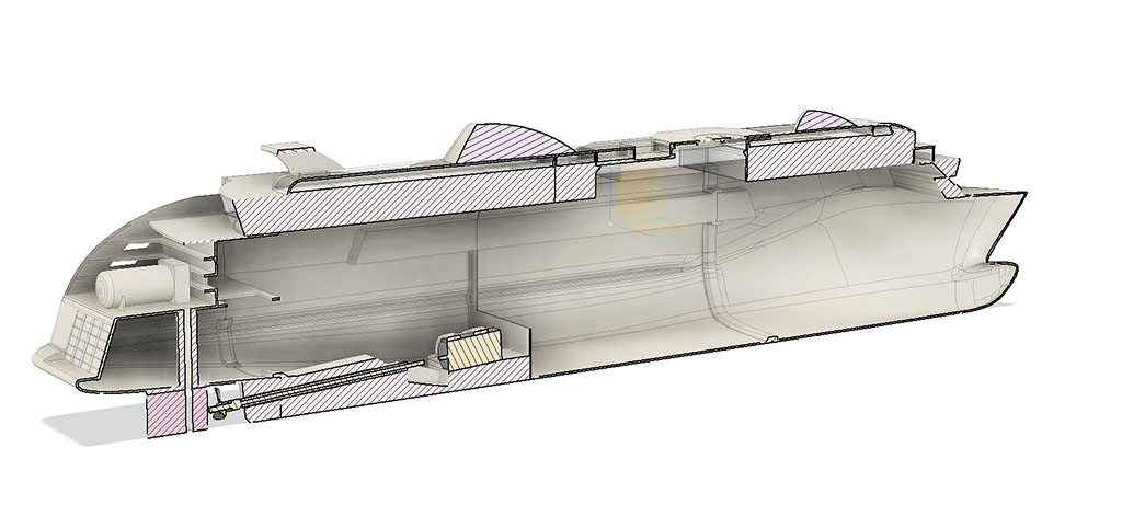
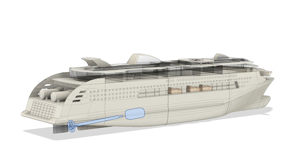
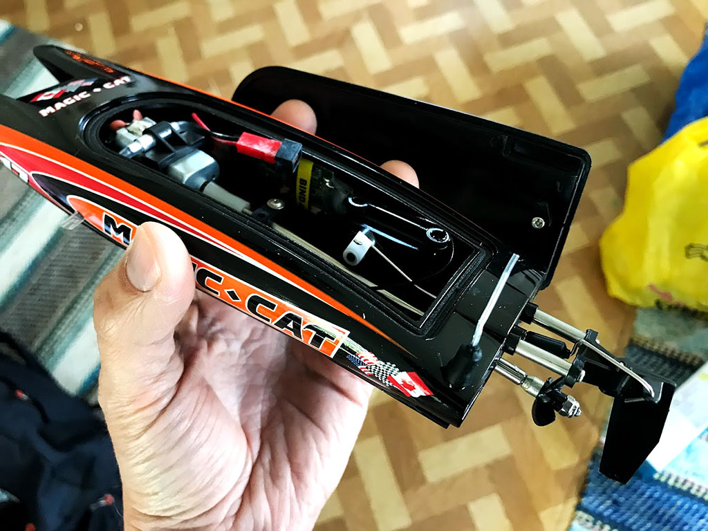
A very useful thing is to draw at least a quick’n’dirty representation of the equipment going in. This makes it a lot easier to adapt the structure for things like engine mount, hole for propeller shaft etc.
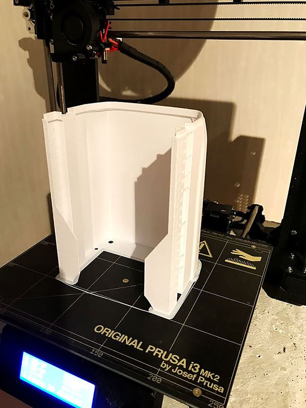
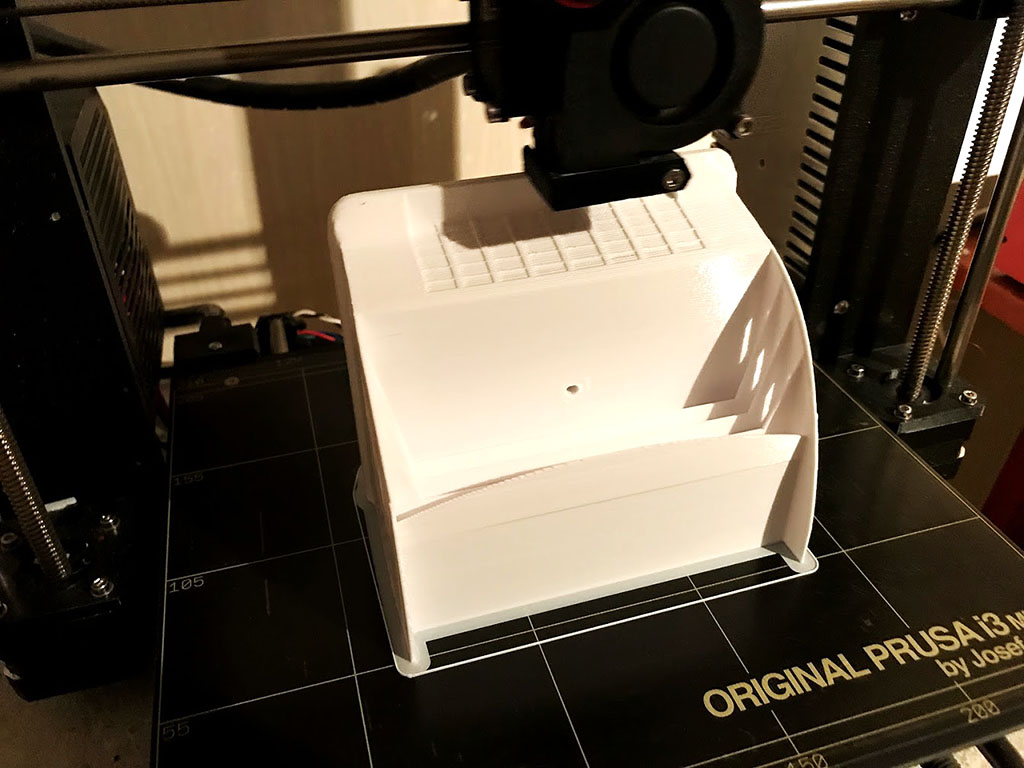
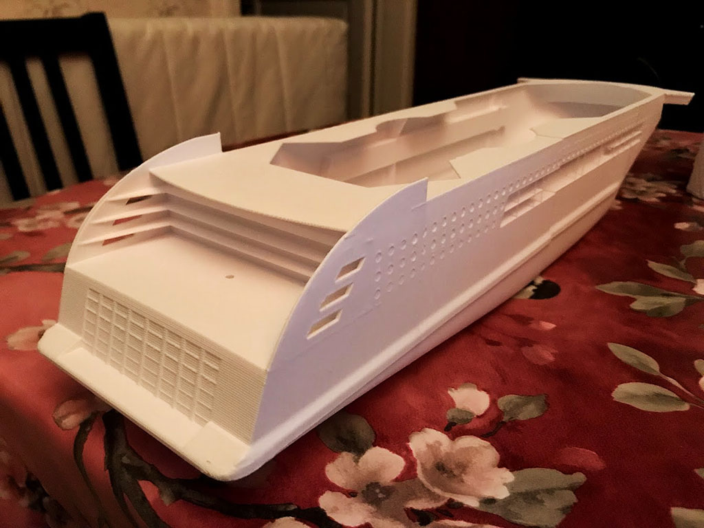
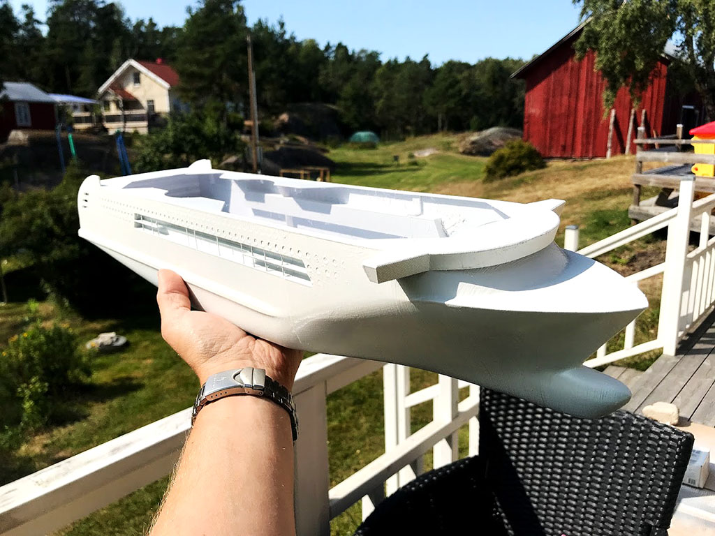
A way to speed up the process was to focus first on the hull sections so they could be put in the printer while I was drawing the superstructure and the rest of the separate details.
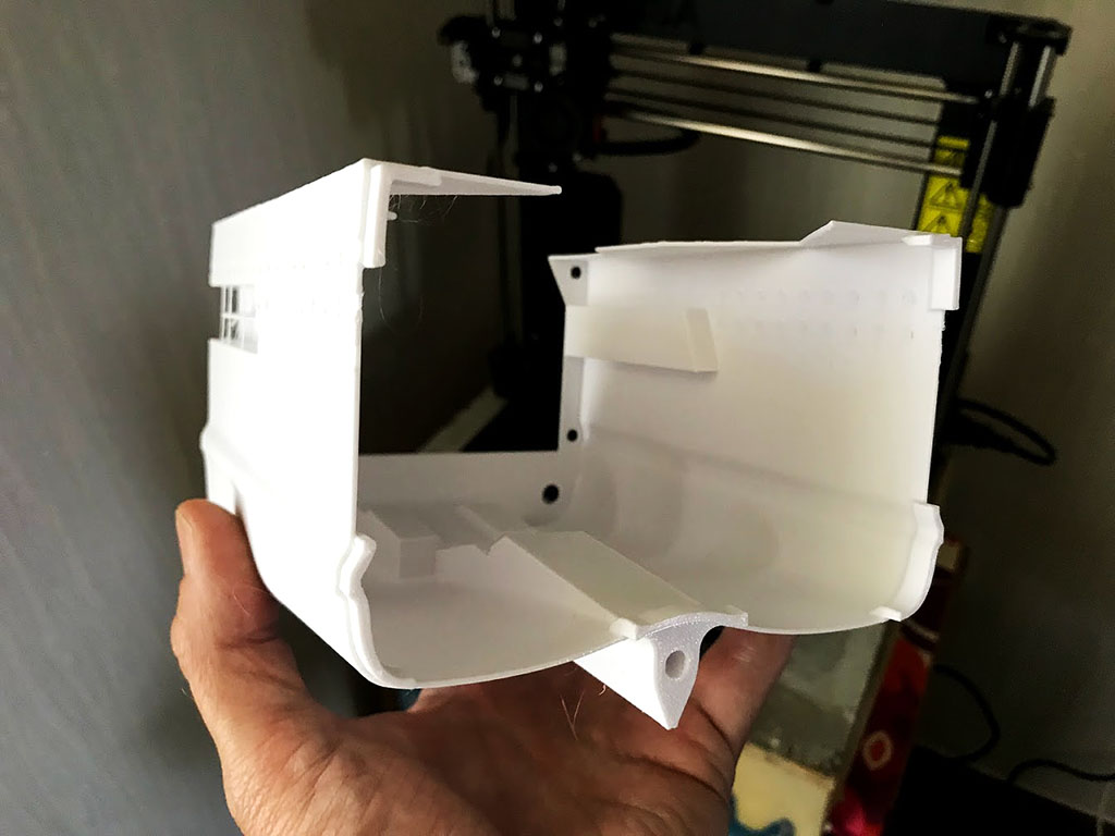
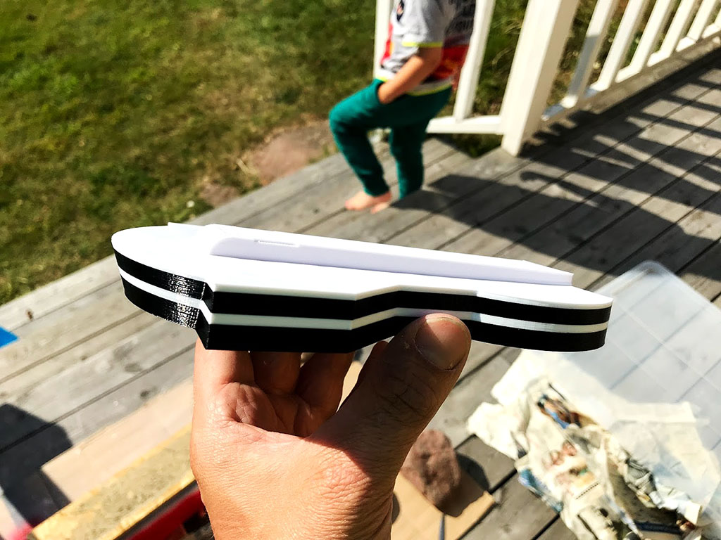
Tabs were added to each sections in order to make the gluing process easier.
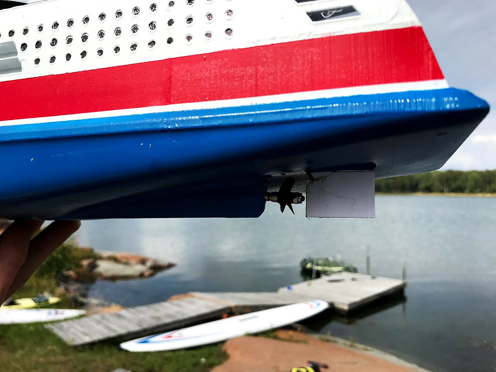
For this build I wanted the ship to be able to rest on a flat surface without the propeller being damaged. In order to do this, I raised the bottom around the propeller. In this way it can be used as a toy on the floor when not using it in water.
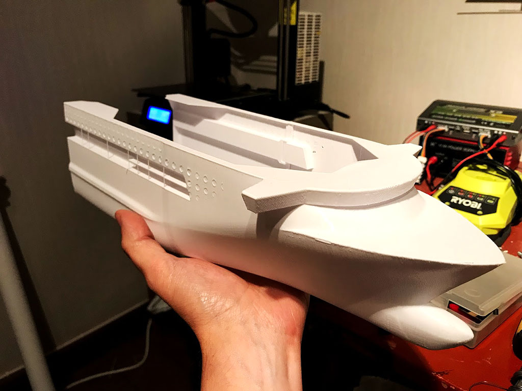
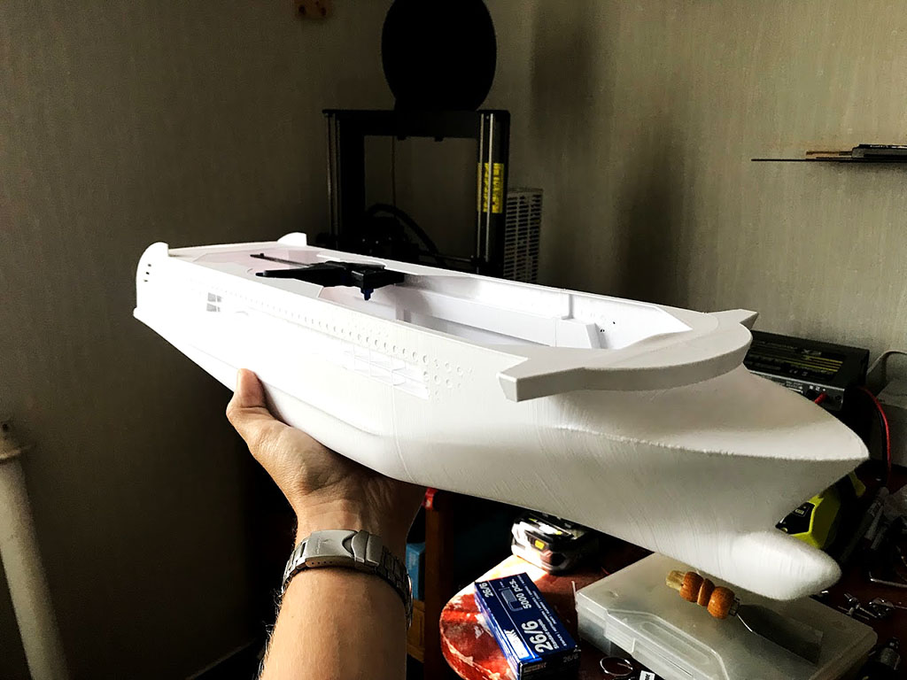
This project had a super-tight time frame so I needed to print as fast as possible. I used 0,25mm layer height and as little support as possible. The sections are glued together using CA-glue and the hull was reinforced with scrap wood and melt glue on the inside as CA-glued joints can be a bit brittle.
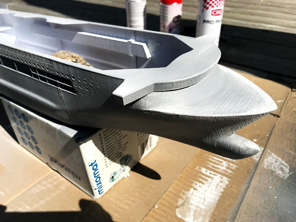
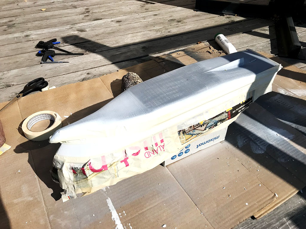
The outside was sprayed with primer and sanded, although I’m far to inpatient to put enough time into it. Had I given this a bit more attention, the quality could be enhanced a lot further.
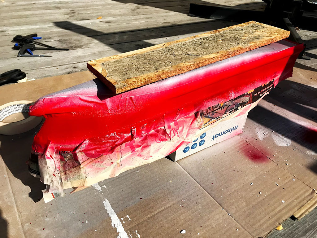
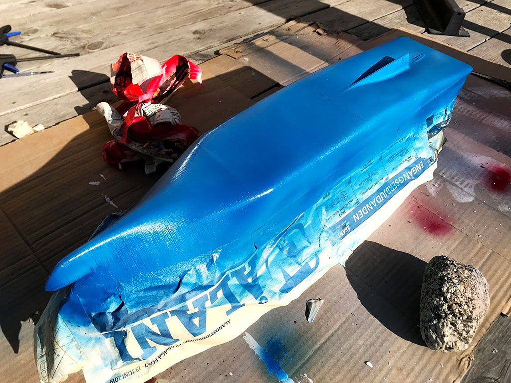
Standard hobby spray paint was used, with 2-3 layers for each color. I really recommend to spend more time on sanding the primer and getting the surface as smooth as possible before painting as that makes the masking tape stick better and you avoid getting leaked paint in cavities in the surface. The lines wasn’t really sharp due to this.
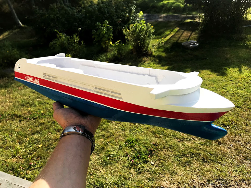
I tried cutting out the viking line text in masking tape because I didn’t have access to a regular printer at our summer house. For future projects I will print decals instead.
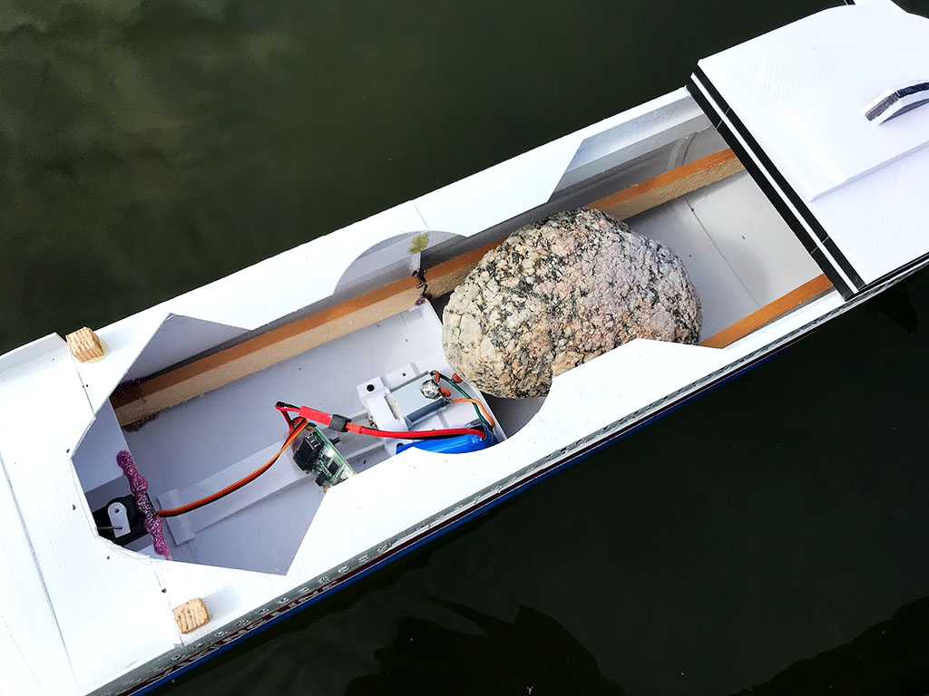
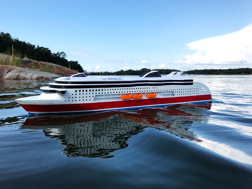
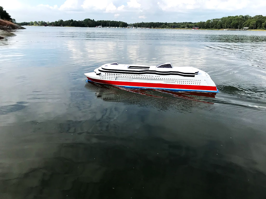
A piece of rock was used as ballast initially and at first I regretted adding so much volume below the waterline, but when testing it in the water it became clear that the extra weight wasn’t so bad after all. It made it a lot more stable and really improved the appearance when it wasn’t bouncing around on every little wave like it would have done otherwise. The relatively high center of gravity also meant it leans in turns, just like the full scale.
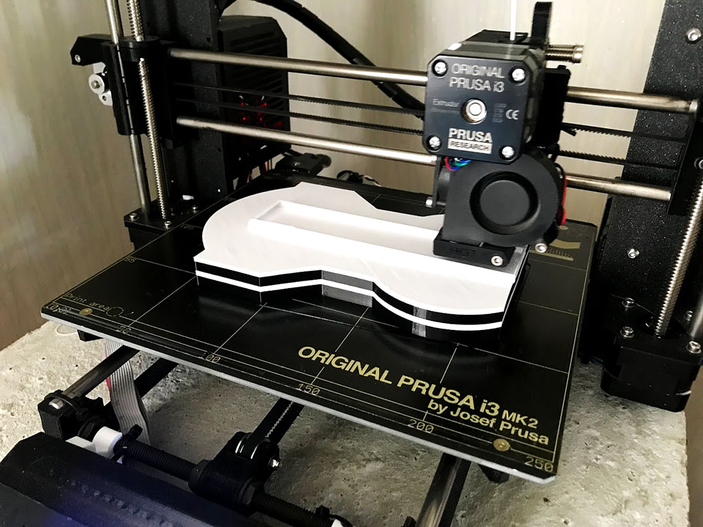
The superstructure was printed horizontally enabling filament swap as a means of getting the right colors. This helped speeding up the build process a lot!
The downside of using the RC equipment we had at hand was that it lacks reverse. I really recommend using a speed controller with reverse. Another idea that I realized after building this was that a bow thruster could be built using drilled holes, silicone tube and a reversible pump. This could be worth exploring for realistic handling!
All STL’s are available for free form Thingiverse.com https://www.thingiverse.com/thing:3800608


