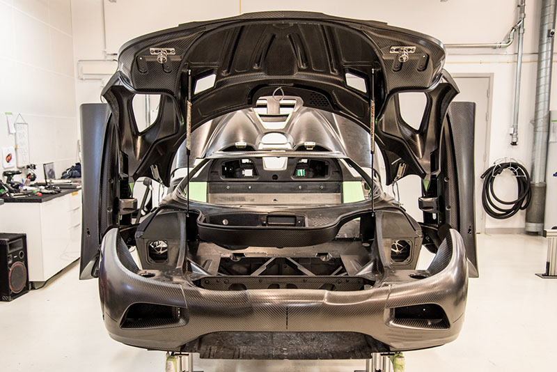
Koenigsegg has always fascinated me even though I’m not particularly interested in cars in general. My interest is more technical. What they have achieved is amazing and has probably not escaped any car enthusiasts notice, but one more unusual aspect stands out – the openness about the process. Not many companies – especially not in highest of high-end – share as much of the process as they do:
https://www.koenigsegg.com/build128-agera-rs-station-2-body-alignment/
Seeing this together with Doug DeMuro’s in-depth review of a particular Keonigsegg Agera RS called the “RS1” got me totally hooked in trying to build a functional scale model using 3D-printing.
Some may debate the need for 4K-videos on Youtube and so did I, until I could walk through this video in dumping screen shot after screen shot!
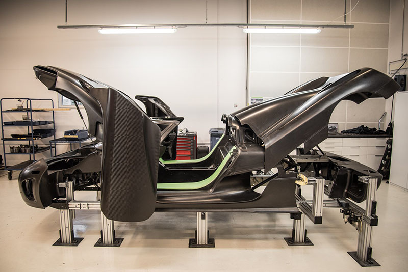
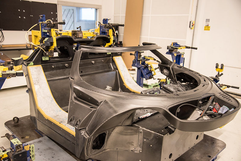
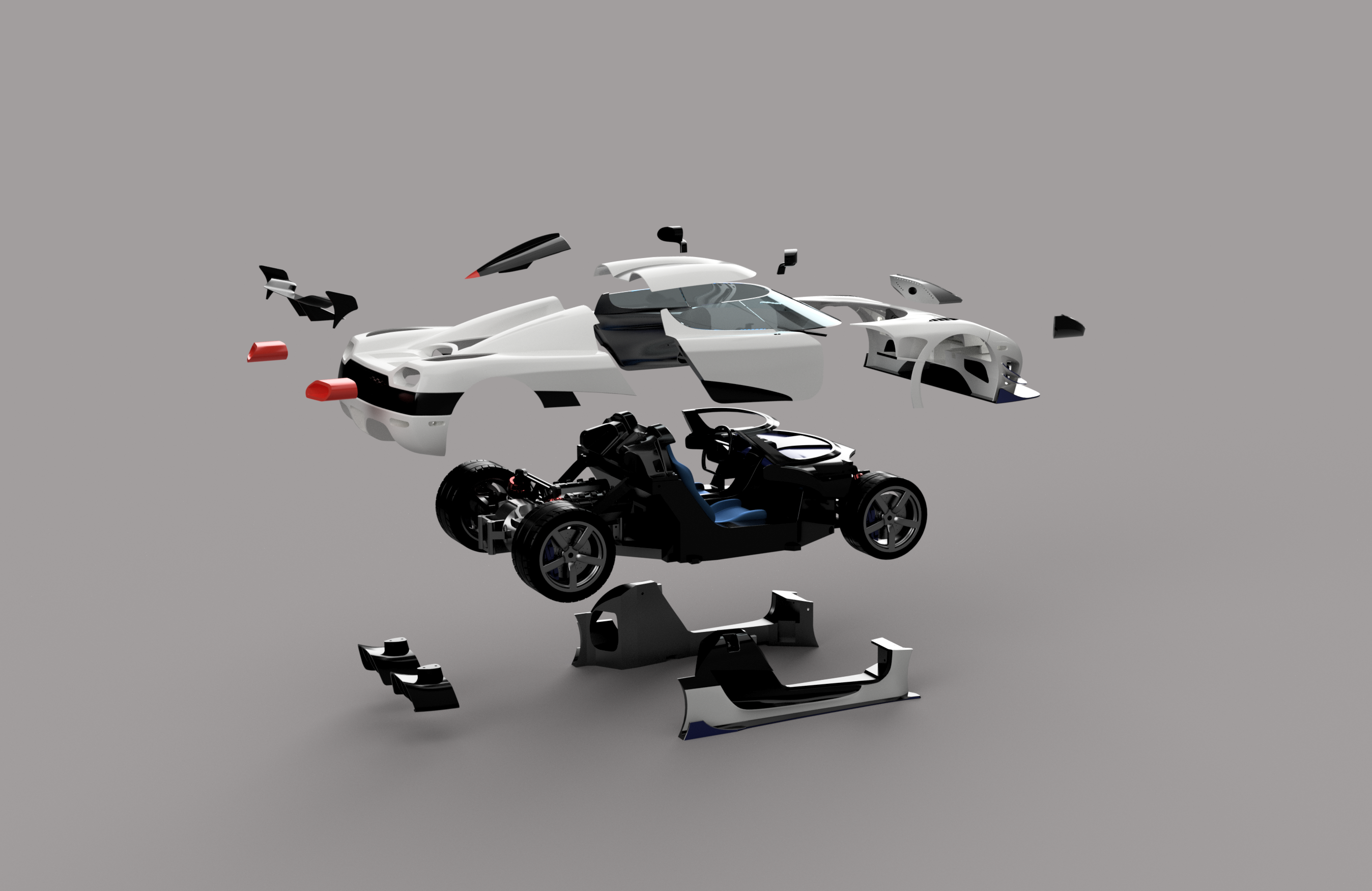
The aim of my project was to create something that not only is scale like on the outside, but also on the inside. This was possible only because of the awesome blog posted by Keonigsegg showing the different structural elements.
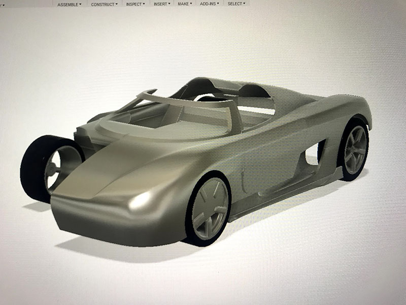
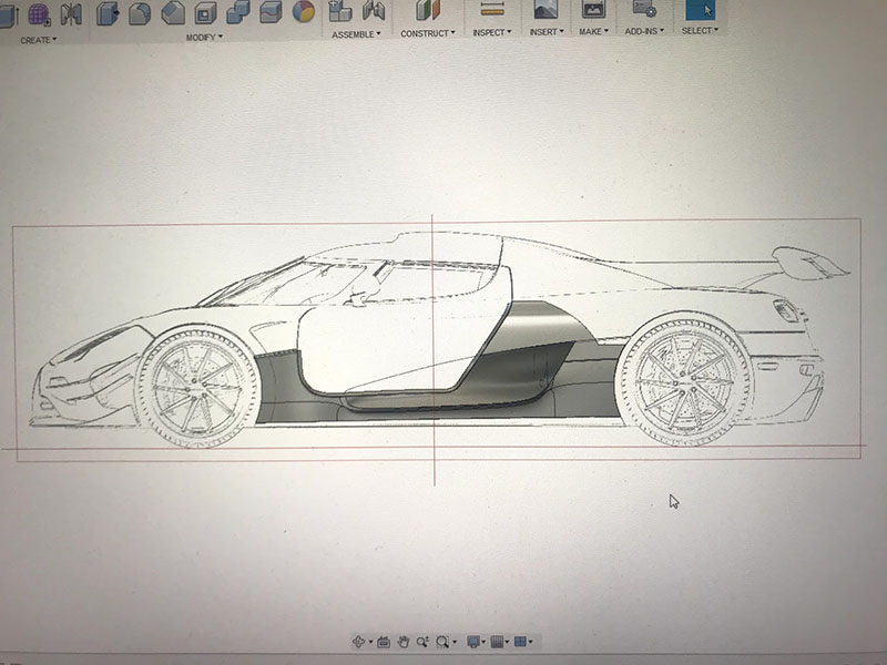
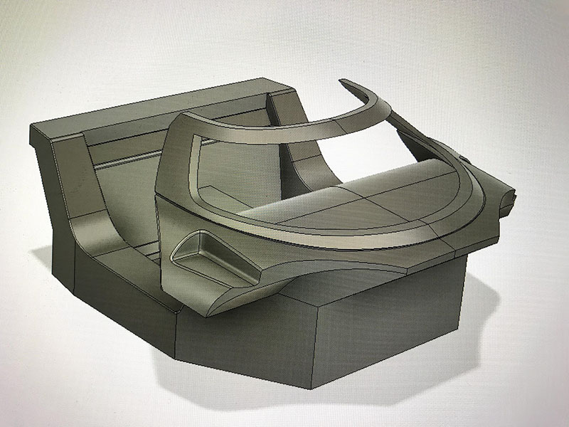
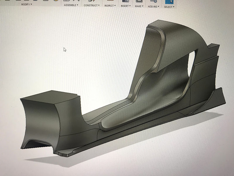
The entire project has been done using Autodesks Fusion 360. It has besides traditional CAD-tools an awesome sculpting feature that let’s you create shapes by draging, pulling, pushing lines and points with the mouse rather than entering exact dimensions in sketches. Although this is a process that is more artistic and needs to be learned differently than traditional CAD, once you’re up’n’running with it, it saves an enormous amount of time. The picture above shows a very early stage of modeling.
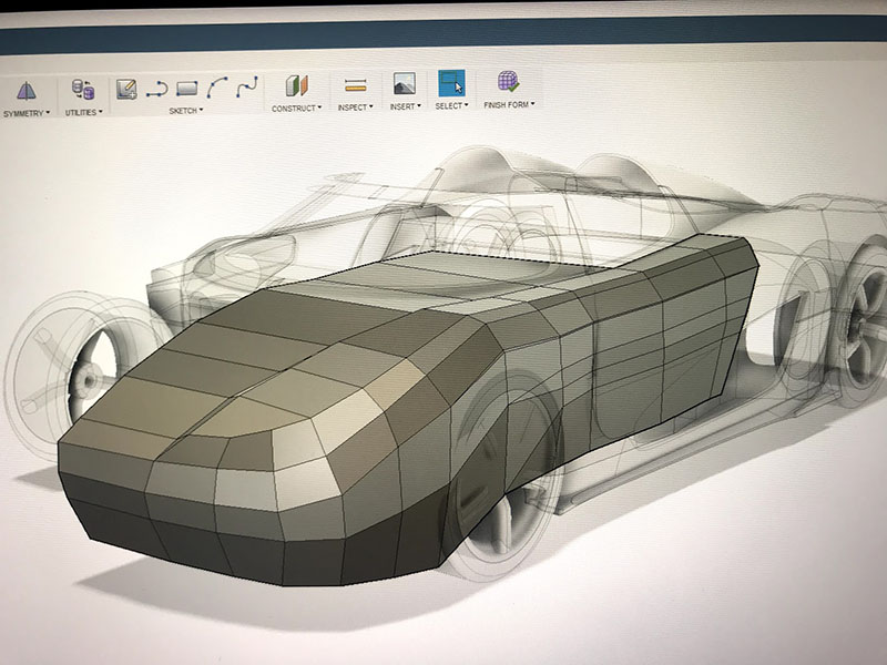
Many people give up at this point because they are working in the rounded mode where one cannot really see what is going on with the individual points and lines in the surface and it’s easy to end up with a lot of errors. In the picture above, display is instead set to box-mode which shows the shapes in polygons with flat surfaces and sharp edges instead. This is the single most important feature I’ve learned and by toggling between box-mode and rounded mode, you can easily figure out what is wrong in the model and sort it out. I work mainly in box mode when creating shapes. The picture below shows rounded mode.
I started modeling the project during our Christmas vacation in Thailand. Working on a small laptop with basically no internet-access most of the time was no problem. The laptop has touchscreen so panning and zooming was possible with my fingers. Not the most time efficient way of modeling, but hard to do it in any other way beside the pool!
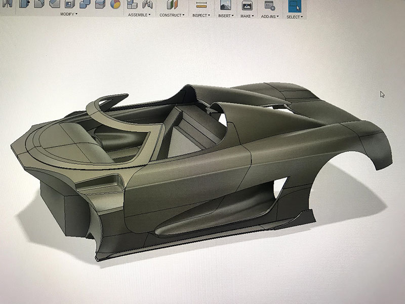
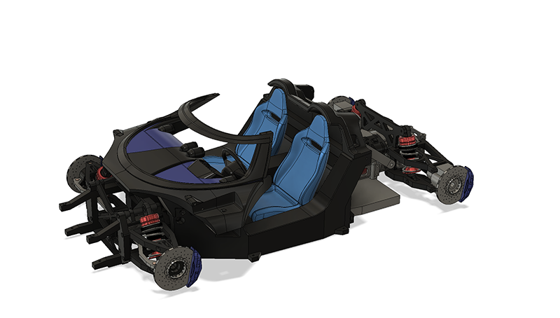
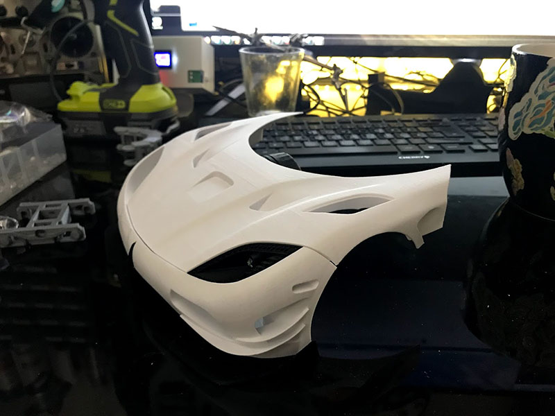
I started with the core structure and worked my way out with the different body segments. Each divided into it’s own component. This is also an important step in order to manage the project. Modeling the entire body in one piece is not convenient, nor practical.
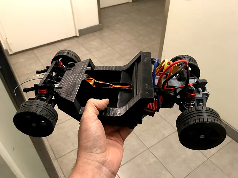
The suspension and transmission is designed more for functionality an the possibility to print as much as possible, rather than exact scale. It is of course a balance between taste and interest. Carbon fiber rods and more hans-on-work could of course be incorporated if one wants also the inside to look as scale-like as possible.
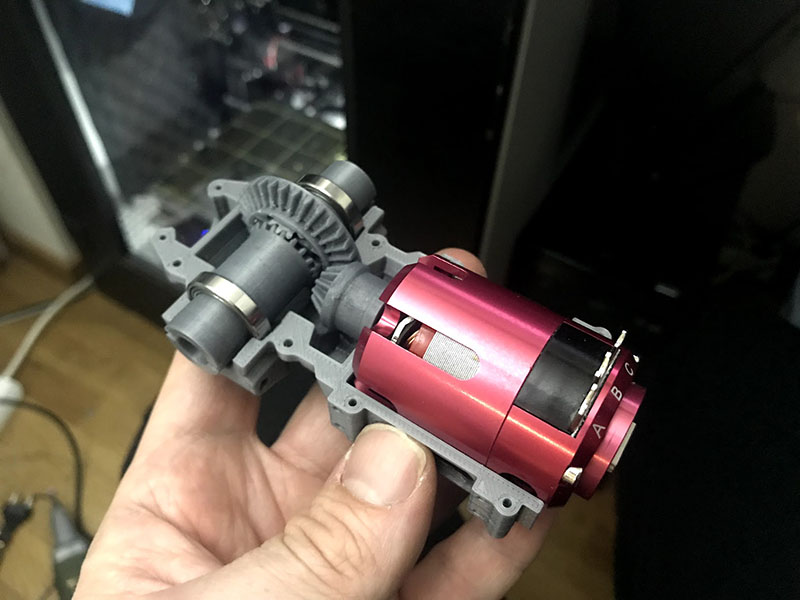
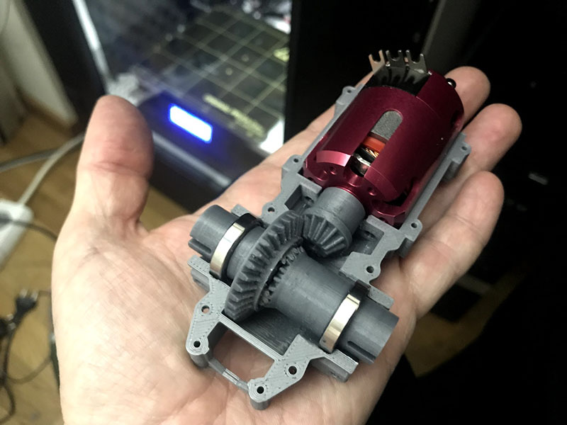
The car is powered by a brushless DC-motor from Hobbyking, and the differential is 3D-printed. I designed two version so it before I was happy. The first one shown in the picture below was too big and way too complicated.
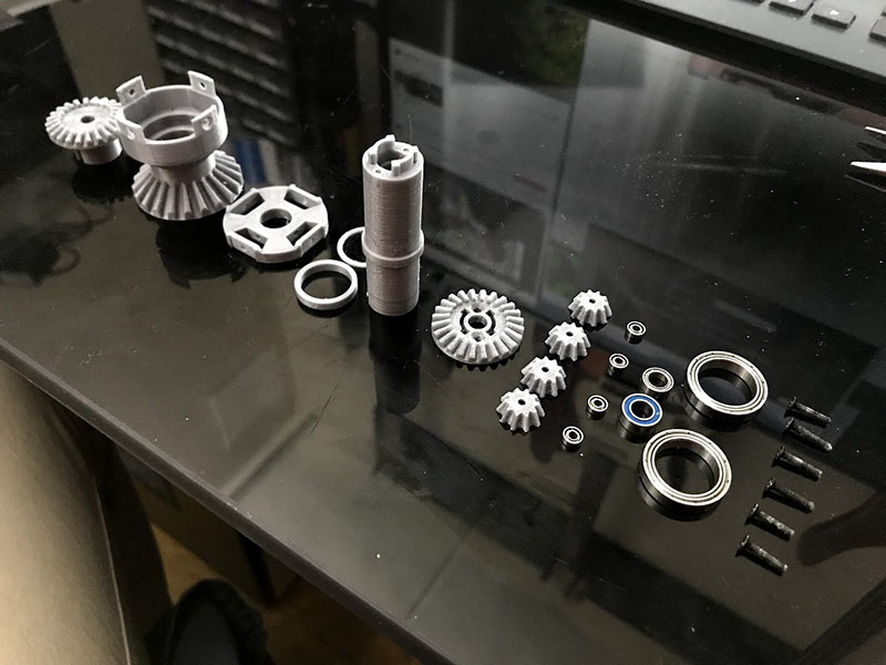
Instead I placed the 4 transfer-gears into the main wheel itself, which saved a lot of space. The ball bearings were removed from the small transfer gears also to be able to make them smaller.
The first set of gears and shafts were printed in PLA. Even though it works, the pinion gear (located on the motor shaft) started to show some visible wear after a couple of high-speed runs in the garage.
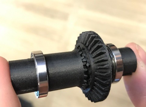
However, https://3dverkstan.se/ was kind enough to print these parts in Onyx on their Markforged X7. With these new gears and some adjustments, the car is almost completely silent! No rumbling gear-noise. It is going to be very interesting to see how they keep up after some more intense driving.
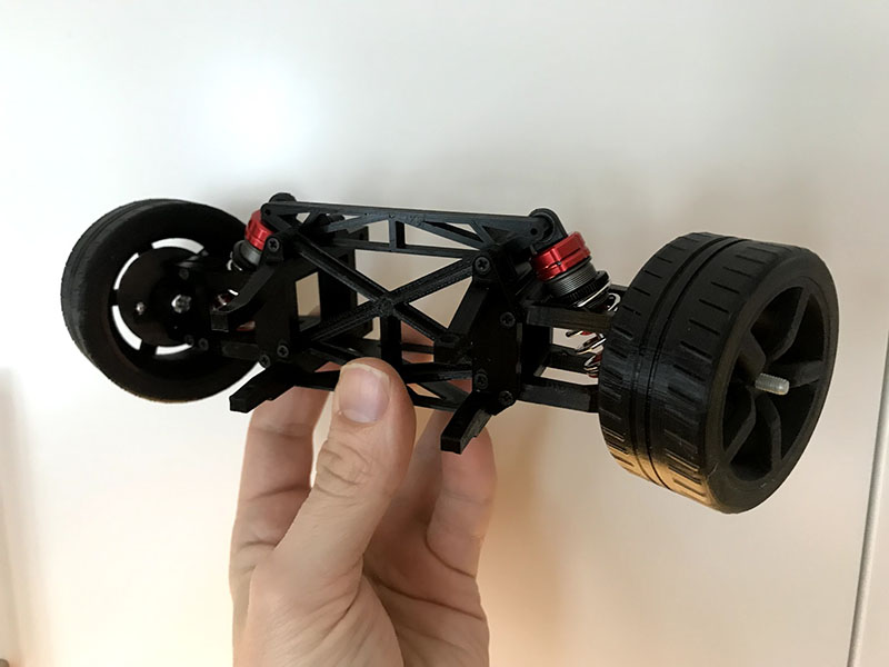
The front suspension is modeled around small metal ball-joints with cavities drawn in the suspension arms. Thanks to the Prusa MK2’s awesome precision, the ball joints work perfectly! Both front and rear suspension uses shock absorbers baught from Hobbyking. All the parts in the picture above except the tires are printed in PLA.
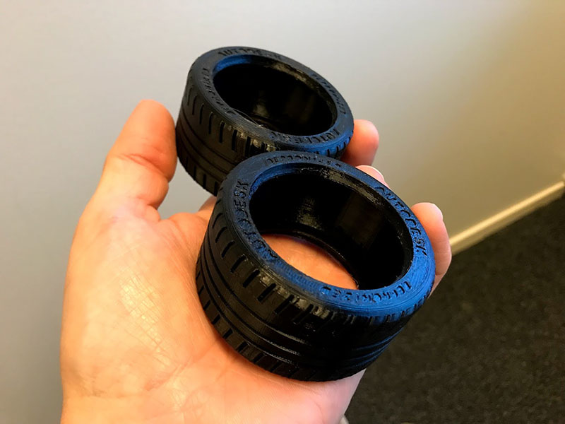
The first se of tires has been printed in TPU95A on the Ultimaker 3. This is a polyurethane based flexible material, but not as flexible as rubber so the grip on flat floor is terrible. Traction on carpet is somewhat drivable, but for it to be really useful, I’m going to have to cast rubber tires. I will post separate posts about this later!
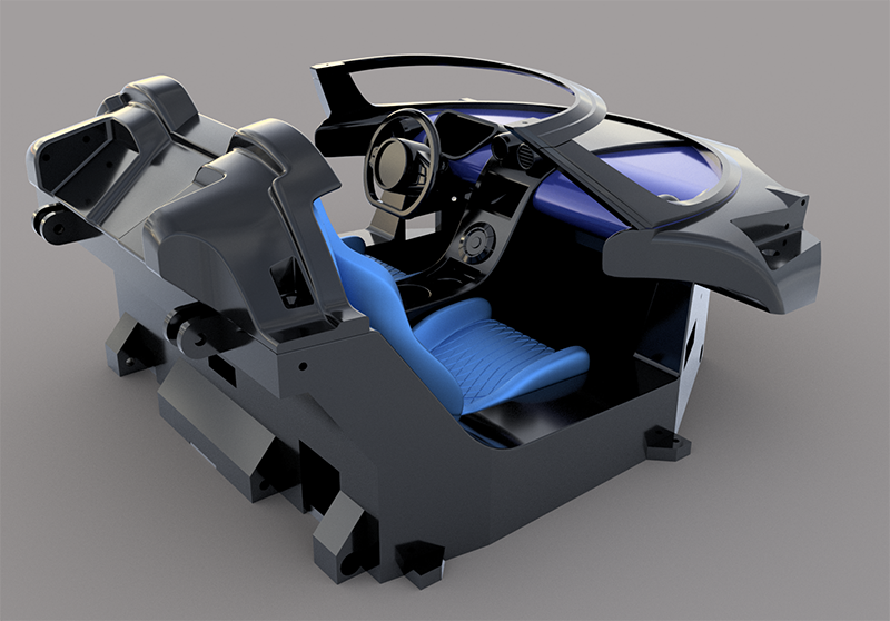
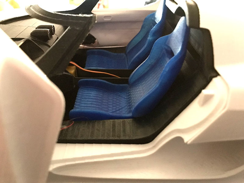
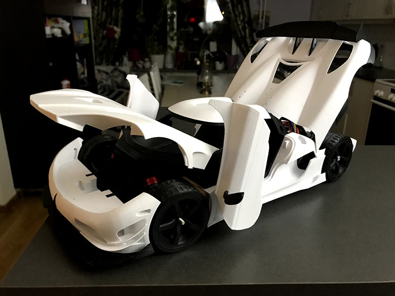
The internal structure nearing completion. On criteria for the build was to be able to hide equipment at least from showing inside the “cockpit”. To be able to do this, I had to place the battery under the seats and the receiver inside the middle console.
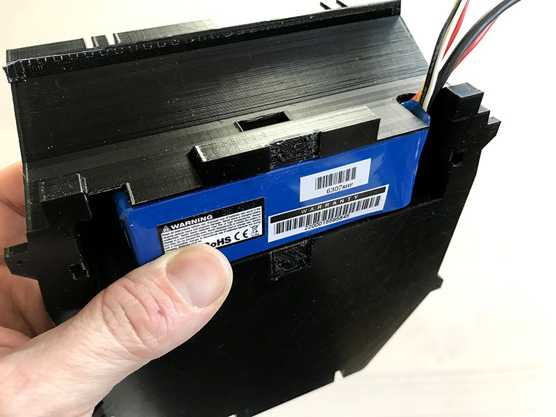
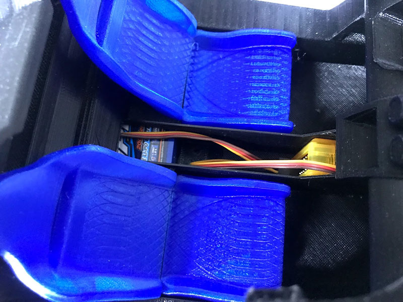
The batteyr is a 3 cell Litium Polymer battery at 1500mAh capacity.
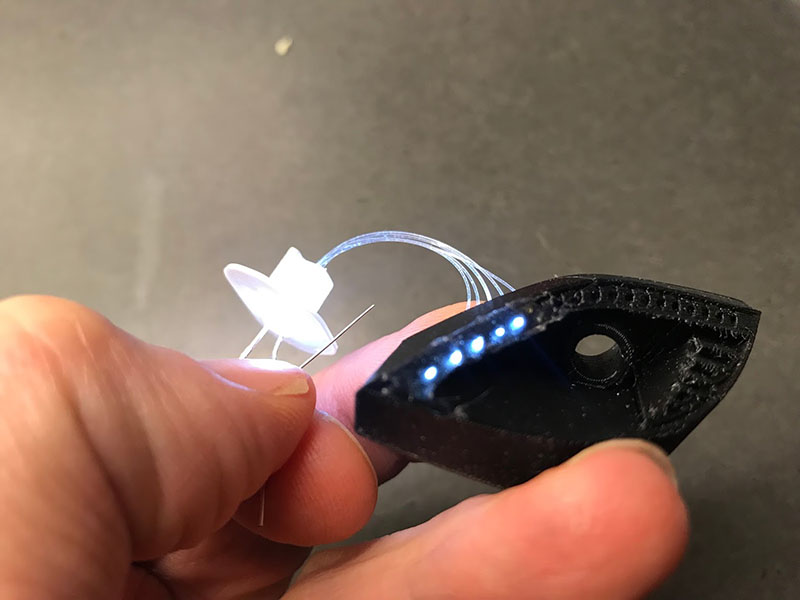
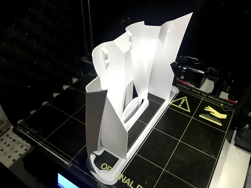
The headlights have a unique shape and one that actually suites this project quite well. Many cars today have extremely complex shapes molded into clear plastics, but the Agera RS has not. Instead it has a lot of small illuminated dots around the perimeter of the light. This was something I wanted to incorporate and the choice of method fell on fiberoptics. The picture above shows the first test using fibers cut from a medusa lamp.
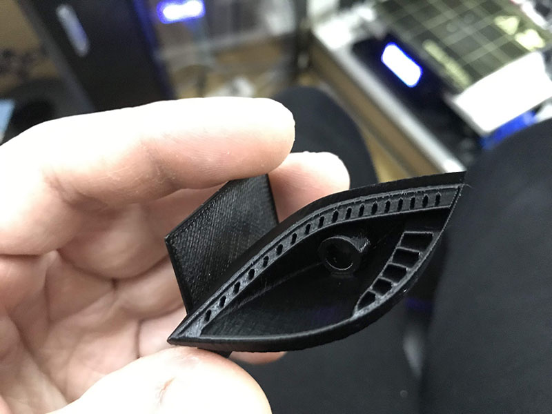
Printing the headlight houses on an FDM printer with good result was a real challenge! it was achieved by careful orientation. The plate visible to the left in the picture was added in the CAD and used as a base, placed on the print bed and then cut off after printing. The first prototype in the earlier picture was placed horizontally and as you can see the difference in quality of the prints is huge!
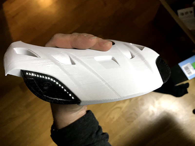

The main beam is produced by a standard white 5mm LED.
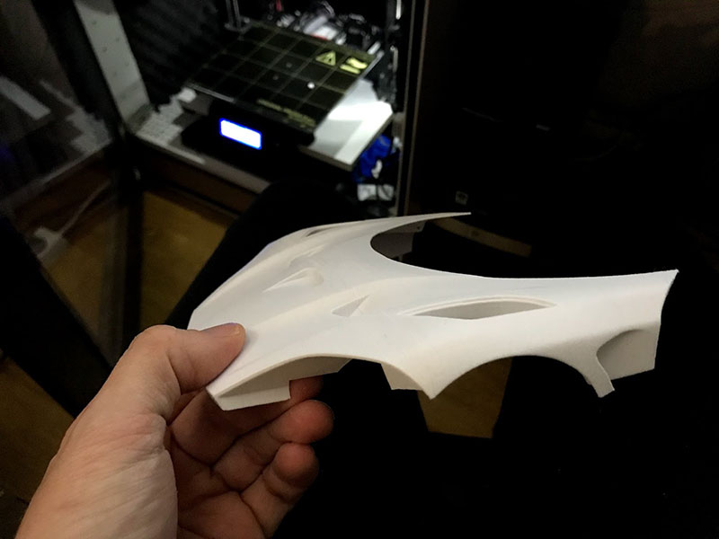
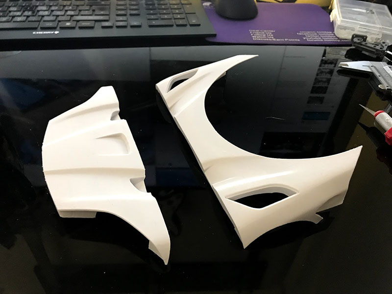
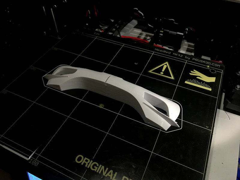
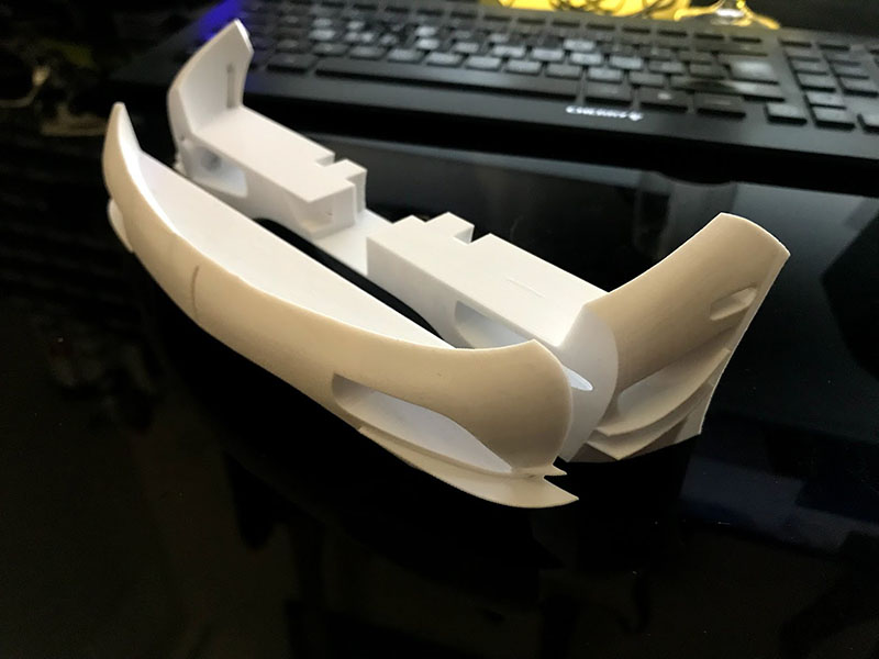
The key to achieve good print results with complex shapes like the body parts above lay in splitting and orienting them correctly on the print bed. A general rule is that vertical surfaces are mostly better than horizontal ones. This might sound counter-intuitive as the layers are stacked vertically, but for horizontal contours with very low angle, the layer edges are very clearly visible compared to a vertical surface where they are so close to each other that they blend into the shape. Another rule is to place the parts with the split to the print bed. This is the most flat “flat” surface you can get, so by doing this you will get a nice and tight fit when you glue the parts together.
Some really big parts can be in need of extra supports. In this picture you can see the rear hood, and that vertical supporting elements has been added to the CAD in order to prevent the piece to sway back and forth when the print bed moves, and also to prevent it from completely be knocked off the print bed completely.
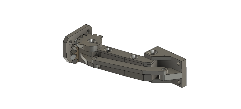
The door hinges called the “Dihedral synchro-helix” was indeed a challenge to model and to get functional using 3D-printed parts. I feel that they require a blog post of their own so I will not describe them more in detail here than to say that the principle is that they provide both swing and rotation in the same motion using an arm and a gear joint. It is a remarkably simple solution technically, with a beautifully complex geometrical movement as a result!
I know there are a lot of details that need more explanations and I’ll try to write more posts about specific topics, this is only the first blog entry about this model, more will come! I will also make the files available one way or the other, so stay tuned!